


14 15MULTICOM PRO-XL MDX4600/PRO-XL MDX2600/AUTOCOM PRO-XL MDX1600 Quick Start Guide
MULTICOM PRO-XL MDX4600/PRO-XL MDX2600/AUTOCO M PRO-XL MDX1600
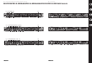
Controls
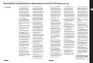
(EN) Controls
(1) Pressing the COUPLE switch links the
channels. In couple mode, dynamics are
controlled by using channel 1 switches and
controls, whereby the control signal is derived
from the energy of both side chain channels
(true stereo processing).
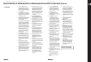
(2) Use the TRIGGER control in the expander/
gate section to determine the threshold below
which expansion sets in, so that signals below
threshold are reduced in gain. The setting
range is from OFF to +10 dB.
(3) If a signal below the adjusted value is applied,
the red LED (expansion on) lights up. If the
signal gain is above the adjusted value,
thegreen LED lights up.
(4) In order to adapt the expander/gate optimally
to the program material, use the RELEASE
switch to select a short or long release time.
Percussive material with little or no reverb at
all is usually processed with a short release
time (switch not pressed). The long release
time is the best choice for slowly decaying or
heavily reverberated signals (switch pressed).
(5) The GATE switch allows you to toggle
between the expander (switch not pressed)
and the gate function (switch pressed).
Usethe gate function to mute signals below
threshold (e.g. noise).
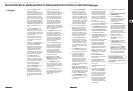
(6) Use the THRESHOLD control to adjust the
compressor threshold from -40 to +20 dB.
(7) These three LEDs (AUTOCOM PRO-XL and
COMPOSERPRO-XL only) indicate whether the
input signal is above or below the adjusted
compressor threshold. The yellow LED in the
middle refers to the IKA “soft knee” range
(ifIKA is on).
(8) Activating the SC EXT switch interrupts
the link between the signal input and the
compressor control section. At the same time,
an external control signal can be fed in via the
rear panel SC RETURN jack, taking over control
of the input signal dynamics reduction.
(9) The SC MON switch links the sidechain input
signal to the audio output, thereby muting the
audio input signal. For example, thisallows
you to pre-monitor the sidechain signal in
combination with an equalizer or other device
inserted into the sidechain channel.
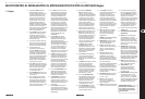
(10) The RATIO control determines the ratio of
input vs. output level with regard to all signals
exceeding threshold by more than 10dB.
Although the compression starts earlier,
the IKA characteristic ensures the smooth,
inaudible onset of the gain reduction, whichis
why the ratio value will be reached only with
10 dB or more above threshold. It can be
set continuously from 1:1 (no compression)
to ∞:1 (limiter).
(11) The 12-digit GAIN REDUCTION display
(MDX4600: 8-digit) informs you about the
current gain reduction applied (1 to 30 dB).
(12) The LO CONTOUR switch activates a high-pass
lter in the side-chain path and thus avoids
the “pumping” eect caused by high-energy
bass frequencies and their inuence on the
compression process.
(13) Use the ATTACK control to determine when
the compression sets in once the signal
has exceeded threshold (MDX1600 and
MDX2600only).
(14) Press the INTERACTIVE KNEE switch to change
from “hard knee” to IKA characteristic:
Inputsignals exceeding threshold by up to
10 dB will be processed with a “soft knee”
characteristic. Above 10 dB the control
characteristic changes from “soft knee” to a
more conventional “hardknee” compression.
(15) The AUTO function, which is activated
with the AUTO switch, disables the
ATTACK and RELEASE controls and derives
these time values automatically from the
programmaterial.
(16) The RELEASE control (MDX1600 and MDX2600
only) sets the time when the original 1:1 gain
is reached, after the signal has dropped below
threshold again.
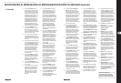
(17) Use the TUBE switch (MDX2600 only) to
enhance the output signal with the warm and
transparent tonal character typically produced
by electronic tubes.
(18) The OUTPUT control allows you to raise
or lower the output signal by max. 20 dB,
so as to make up for a gain loss caused by
the compressor or limiter action. Raise the
gain by roughly the same amount that
it has been reduced by the compressor.
TheGAIN REDUCTION display (11) reads the
valueadjusted.
(19) The 12-digit INPUT/OUTPUT LEVEL
display (MDX4600: 8-digit) reads both
the level of the incoming audio signal
and the level at the dynamics processor
output. The range is from -30 to +18 dB
(MDX4600: -24 to +18 dB).
(20) The IN/OUT METER switch selects
whether the gain LEDs read the input
signal (switchpressed) or the output signal
(switchnot pressed).
(21) The IN/OUT switch activates the
corresponding channel. It provides a
so-called “hard bypass”, i.e. if it is OUT or
the unit is not connected to the mains,
the input jack will be linked directly to the
output jack (COMPOSER PRO-XL MDX2600
only). Usually,this switch is used for direct
A/B comparison between unprocessed and
compressed/limited signals.
(22) LEVEL control (MDX1600). The AUTOCOM
PRO-XL features an adjustable enhancer,
onwhich you can set the amount of treble
boost with the LEVEL control.
ENHANCER switch (MDX2600 and MDX4600).
Activates the dynamic enhancer.
(23) ENHANCER LEVEL. The LED chain reads the
current treble boost within a range from
-30to 0 dB (MDX1600 only).
(24) IN/OUT switch (MDX1600). Use this switch
to activate the enhancer circuit, e.g. to
assess the eect the enhancer has on the
audiosignal.
(25) LEVEL control (MDX2600). Instead of an
adjustable enhancer, the COMPOSER PRO-XL
has a controllable de-esser, which helps you
eliminate hiss noise contained in the audio
signal. The LEVEL control determines the
amount of frequencysuppression.
DE-ESSER switch (MDX1600). The AUTOCOM
PRO-XL also has a de-esser. At the touch of
a button you can enhance the audio signal
considerably, especially when processing
vocal recordings. Switch (25) can be found in
the compressor section.
(26) DE-ESSER LEVEL (MDX2600). The LED chain
reads the current attenuation within a range
from +3 to +12 dB.
(27) MALE switch. This switch adapts the
de-esser to the male (switch pressed)
orfemale registers (not pressed).
(28) IN/OUT switch. Switches the de-esser on
and o.
(29) The peak limiter limits the signal to an
adjustable level. When the LIMITER control
is turned fully to the right, the limiter is
switched o. Owing to its extremely fast
“zero” attack, this circuit is capable of
limiting signal peaks without any overshoot.
If the signal is limited for more than 20 ms,
the overall gain is reduced for about 1 s to
avoid strong and thus audible limiter eects.
(30) The LIMIT LED lights up as soon as the limiter
is on.
(31) FUSE HOLDER/VOLTAGE SELECTOR.
MAINS CONNECTION.
(32) OUTPUTS. These are the audio outputs
of your dynamics processor. The two
matching ¼" TRS and XLR connectors are
wired in parallel and balanced. Of course,
unbalancedcables can be connected here
as well.
(33) OPERATING LEVEL switch. This switch can
be used to adapt the COMPOSER PRO-XL,
AUTOCOM PRO-XL or MULTICOM PRO-XL
to various operating levels, i.e. to toggle
between home recording level (-10 dBV) and
studio level (+4dBu). The level meters will
be referenced automatically to the nominal
level adjusted, so that the compressor works
in its optimum operating range.
(34) INPUTS. These are the audio inputs. They are
also on balanced ¼" TRS and XLR connectors.
(35) SIDECHAIN SEND. This is the unbalanced
sidechain output, which allows you to
route the audio signal to other devices for
externalprocessing.
(36) SIDECHAIN RETURN. The sidechain input
allows you to use an external signal or the
processed (e.g. with an equalizer) audio
signal routed from the SIDECHAIN SEND
jack to control your COMPOSER PRO-XL or
AUTOCOM PRO-XL.
For more details on the full functionality
of this product, see the product page on
behringer.com and download the full manual.