


13TUBE ULTRAGAIN MIC200 User Manual TUBE ULTRAGAIN MIC200 User Manual
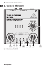
2.1 User interface
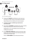
(1) The GAIN control allows you to control the gain from +26 to +60 dB to
the input signal. This control should be set all theway to the left when (dis)
connecting a sound source from the MIC200. When all connections are made,
slowly start raising the gain control.
(2) We recommend using the LED meter to adjust gain. The LED chain displays the
output signal level in dB. Please make sure that the clip LED never lights up
permanently. It should light up only at peak signals, but it should never be on
all the time.
(3) If your MIC200 is connected to the mains via the enclosed power supply unit,
the POWER LED lights up to indicate that your MIC200 is running.
(4) The 20 dB PAD switch reduces the input sensitivity by 20 dB (switchpressed).
The appropriate setting depends on the equipment connected. Generally
speaking, lowering the signal level in mic applications is not recommended.
No matter what your application is, the clip LED warns you to reduce the gain
setting to avoid distortion.
(5) This +48 V switch activates the phantom power supply for the XLR input.
Phantom power supply is required for operating condenser microphones.
Dynamic microphones require no phantom power.
(6) Press the LOW CUT switch to eliminate undesired subsonic noise, such as
oor rumble.
(7) With the PHASE REVERSE switch, the input signal is reversed by 180°.
This function is available for both mic and line signals. Use this function
in a multi-microphone setup if you detect phase cancellations in specic
frequency bands.