


8
EURODESK MX2442A
2.3 Power Supply Unit (PSU)
In common with most desks of this size, the EURODESK has several hundreds of line level operational
amplifiers (op-amps) inside. When being driven hard, many desks begin to show signs of stress due to power
supply limitations. Not so with the EURODESK. Due to the vast power resources of its external power supply
unit, the sound should stay clean and crisp and tight right up to the operating limits of the op-amps themselves.
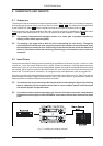
The EURODESKs external PSU connects to the desk at the rear of the console via a multiway connector.
Give an extra 1/2 U of rack space to allow air to circulate around the heatsinks employed for heat dissipation
since the EURODESK PSU chucks out a massive 100 Watts.
Please note:
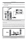
On the rear of your PSU you will find the mains connector / fuse holder / voltage selector. Before you connect
the unit, please make sure that the displayed voltage corresponds to your mains supply.
If you intend to change the operating voltage, remove the fuse holder and twist it by 180 degrees before you re-
insert it. Matching the two markers indicates the selected voltage.
Note that the correct fuse type and rate must be installed, corresponding to the mains voltage.
Connect the PSU to the mains power supply by the enclosed mains cable, then use the mains switch to power
up your power supply unit and EURODESK.
+ Never connect or disconnect your EURODESK and power supply unit when the power supply
unit is on! Always start connecting your MX2442A to the PSU, check if the PSU is turned
off, plug into mains and then power up the PSU and thereby your EURODESK.
3. MONO INPUT CHANNELS
Each channel comes with a balanced line level input on 1/4" TRS jack, and an XLR mic input. Press the
PHANTOM switch at the back panel if required. The mic amp circuit ( ) has an unusually wide gain
range from 10 dB to 60 dB, is of extreme low-noise design, and utilizes high-current conjugate pair vintage
transistor circuitry to deliver an incredibly warm and transparent sound.
When a jack is plugged into the balanced (self-unbalancing) line input, the gain structure can match any line
level from +10 to -40 dBu. The crucial operating levels +4 dBu and -10 dBV are clearly and accurately legended
( ).
3.1 Input Level Setting
The channel input level is determined by the GAIN trimpot . Use SOLO/PFL to accurately monitor the
channel input on the left/right master output bargraph meters. This also sends the SOLO/PFL-ed signal to the
left and right speakers.
+ For level setting (as opposed to localized listening) choose to use the mono PFL bus rather
than the post-fader (post-channel pan) stereo solo bus (CHANNEL MODE switch not
depressed). SOLO/PFL never interrupts the mix at the main recording outputs. It follows that
aux sends and subgroups must also be unaffected, since they contribute directly to the main
mix.
In addition to switchable SOLO/PFL metering, a couple of channel LEDs ( / ) illuminate when a signal
is present (-20 dB), or if a channel is going into overload. These LEDs are particularly useful when using
extreme EQ settings, or adding a dynamics processor via an insert.
You do not want the overload light to come on except very intermittently during a take or a mix. If it does light
persistently, reduce the input gain (see also the essential section 8: SETTING UP).
3. MONO INPUT CHANNELS