


8 EUROPOWER PMP1000/PMP3000/PMP5000 User Manual
The (41) FX 1/2 TO MON 2 control allows you to determine the effect intensity
of the multi-effects processor in the monitor 2 mix. No effect is sent to the
monitor 2 mix with this control turned fully counter-clockwise.
The (42) FX 1/2 TO MAIN control allows you to determine the effect intensity of
the multi-effects processor in the main mix. No effect is sent to the main mix
with this control turned fully counter-clockwise.
PMP1000: The FX TO MAIN control performs the same function as on the
PMP3000 and PMP5000.
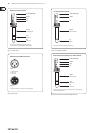
Main and monitor section2.4
(43) The SURROUND control determines the effect intensity.
This is a built-in effect, which widens the stereo
panorama, thus making the sound more lively
and transparent.
Press the (44) XPQ TO MAIN switch to activate this effect.
Pressing the (45) AFL switch (after-fader listening) activates the solo function.
If AFL is on for the corresponding channel in the main section, you will only
hear the signal from this channel. Its volume can be adjusted with the fader.
Switching AFL on has no effect on the main or monitor mix, as long as you
don’t move the fader. In this way, you can monitor one or several selected
signals via the PHONES/CTRL jack (65). When AFL is on, the corresponding
control LED illuminates.
The PMP1000 does not have an AFL function.◊
PMP1000: (46) FX SEND fader.
PMP3000: FX fader.
PMP5000: FX 1/2 fader.
This is the master send fader for the signal routed to the effects processor
and to the FX SEND output (63) (see also (11) and (12)).
PMP1000: (47) MON SEND fader.
PMP3000/PMP5000: MON 1/2 fader.
These faders are used to set the monitor output volume
(see also (9) and (10)).
PMP1000: The main mix allows you to control the volume from the Main 1 (48)
output with both faders.
PMP3000/PMP5000: The MAIN 1 fader controls the volume of the
EUROPOWER. The main signal is also provided at the MAIN 1 output
(see also (58)).
PMP3000/PMP5000: The (49) MONO fader controls the mono mix signal
(see also (63)).
PMP5000: The (50) SUB FILTER filters out frequencies above the selected
setting, so that only low frequencies are sent to an (active) subwoofer via the
MONO OUT (63)). Set this switch to “On” to activate the filter.
PMP5000: The (51) SUB FREQ control determines the cut-off frequency for the
subwoofer output. This value can be adjusted from 30 to 200 Hz.
The (52) PHONS/CTRL R control adjusts the headphone or control room volume
(see also (65)).
PMP3000/PMP5000: The (53) MAIN 2 control determines the volume at the
MAIN 2 output (see also (59)), which is the same signal as at MAIN 1, but with
extra output jacks and separate volume control.
PMP3000/PMP5000: With the (54) CD/TAPE IN control you can adjust the volume
of the line signal present at the CD/TAPE INPUT (55). Use the PFL switch to
monitor the signal.
PMP1000: With the CD/TAPE RET fader you can adjust the line signal
applied to the CD/TAPE INPUT (55). Use the CD/TAPE MUTE switch to mute
the channel.
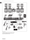
Connectors2.4.1
Use the (55) CD/TAPE INPUT jacks (RCA) to connect an external stereo signal,
such as a CD player, tape deck or other line-level sources.
(56) The VOICE CANCELLER filters vocal-specific frequencies from
the CD/TAPE INPUT signal. This function can be used for
karaoke, i.e. you can remove the vocals from a song and then
sing along with the music yourself.
The (57) CD/TAPE OUTPUT provides the line level stereo signal (e.g. for a
DAT recorder).
If the CD/TAPE OUT signal is connected to a recording machine whose ◊
output signal is returned to the CD/TAPE IN, feedback can occur
when you activate the record function on the recording machine.
So, disconnect the CD/TAPE IN from the recording machine before you
start recording or set the CD/TAPE input signal to zero!
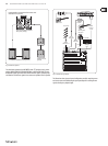
PMP1000: The (58) MAIN OUT jacks allow you to send the main line level signal
to an external amplifier, when, for example, you want to use the mixer and
effects section. The PMP3000 and PMP5000 have two separately controllable
line level MAIN outputs (59) (MAIN 1/2).
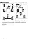
Connect your monitor power amps or active monitor speakers to the (59)
MON 1/2 SEND to monitor the signal mix created with the MON controls or
to route it to the musicians on stage.
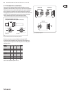
The PMP Series comes with a POWER AMP INSERT connection that is (60)
provided for various applications. This connection enables you to use the
power amplifier of the device to amplify the output signal of another
preamp. For example, it is possible to connect a larger mixer or preamp
output (line signal) of an instrument amplifier. In this case, you only need an
unbalanced, mono jack cable.
Furthermore, it is possible to use the POWER AMP INSERT as a conventional
insert to add a compressor or graphic equalizer to the signal path,
for instance. Here, a balanced, stereo jack cable is required and the
assignment of tip and ring needs to be observed according to Figure 4.5
(see Chapter 4.2 “Audio Connections”). In this case, the ring is the so-called
Send, which is connected to the input of the additional device, and the
tip is referred to as Return, which is connected to the output of the
additional device.
Lastly, it is possible to tap the output signal of the device’s mixer section
from the POWER AMP INSERT in order to use a second, external power
amp. A balanced, stereo jack cable is required with the ring (not the tip)
connected to the input of the external power amp. If you want to use the
internal and external power amps at the same time, just wire the connector’s
ring and tip together.
The (61) FOOTSWITCH jack is for a standard footswitch. You can activate an
“effect bypass”, thereby muting the effects processor. Use a dual foot
switch for the PMP5000, so that you can enable/disable FX 1 and FX 2
independently of each other. In this case, the tip of the ¼" plug controls FX 1,
and the ring FX 2.