


7 EUROPOWER PMP1000/PMP3000/PMP5000 User Manual
Caution! Never use unbalanced XLR connectors (pins 1 and 3 ◊
interconnected) on the MIC input jacks, if you are going to use the
phantom power supply.
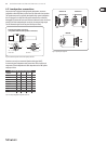
The (27) AMP MODE switch determines the mode of operation of the PMP
amplifier stage:
PMP1000:
MAIN: In the “MAIN” position the mixer works as a stereo amplifier.
MON: In this mode the monitor signal is present at OUTPUT A (71) and the
main signal at OUTPUT B (70) (both are mono).
BRIDGE (bridged mono mode): In BRIDGE AMP MODE the output power
of OUTPUT A is added to that of OUTPUT B, i.e. OUTPUT B delivers twice its
normal output power.
PMP3000/PMP5000:
MAIN L/MAIN R. In position MAIN MIX, the mixer works as a
stereo amplifier.
MON 1/MONO. In this mode the monitor 1 signal is present at OUTPUT A
(71) and the main signal at OUTPUT B (70) (both are mono).
BRIDGE (bridged mono mode): In BRIDGE AMP MODE the output power
of OUTPUT A is added to that of OUTPUT B, i.e. OUTPUT B delivers twice its
normal output power.
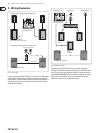
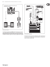
In BRIDGE mode, always connect only one loudspeaker with an ◊
impedance of at least 8 Ω to the OUTPUT B jack! Please note that
OUTPUT A must NEVER be used in BRIDGE mode!
In all other operating modes, the minimum impedance of the speaker ◊
must not fall below 4 Ω.
Please note that the power delivered to the speaker connected to ◊
OUTPUT B in BRIDGE AMP MODE is considerably higher than the power
provided to the speakers wired to the parallel speaker outputs.
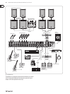
Please read the information given on the rear panel of the power mixer.
Information on how to properly connect your speaker with regard ◊
to polarity can be found on the rear of the unit (PIN assignment)
(see also (71) and (72)).
PMP5000: Use the (28) BEHRINGER SPEAKER PROCESSING switch to activate
a filter that allows you to adapt the mixer to the characteristics of your
loudspeakers. If the speakers have a limited frequency response in the bass
range, this function allows you to filter this range at the output signal of the
mixer and thus adapt it optimally to the frequency response of the speakers.
PMP1000/PMP5000: If (29) STANDBY is pressed, all input channels are muted.
During pauses you can prevent the microphones from picking up noise
or interference, which would then be reproduced by the P.A. system or
possibly damage the speaker diaphragms. The benefit is that all faders can
be left untouched while you play back music from CD via the CD/TAPE inputs
(see (55)). There is also no need to move the faders and lose your mix.
Equalizer and FBQ2.2
Your power mixer features a graphic 7-band equalizer, which allows (30)
you to fine-tune the sound depending on the room acoustics. In the
center position the frequency response is not effected. To boost or cut a
certain frequency range, simply move the corresponding fader upward or
downward respectively.
Please note that the equalizer behaviour depends on the position of ◊
the AMP MODE switch (see (27)).
(31) Press the FBQ IN switch to activate the Feedback Detection
system (the FBQ will be active only if you have switched on
the equalizer (33) before). Frequencies causing feedback are
shown by brightly lit fader LEDs. All other LEDs will be darker.
Now, cut the frequency range in question until feedback disappears (the LED
gets darker or goes out). This function is available for both the main and
monitor mix.
PMP1000: The switch FBQ FEEDBACK DETECTION performs the same
function as on the PMP3000 and PMP5000.
Use the (32) MAIN/MON 1 switch to select whether the equalizer processes the
main or the monitor mix. When not pressed, the stereo equalizer processes
only the main mix. When the switch is pressed, the EQ processes only the
monitor mix.
PMP1000: The MAIN MIX/MONITOR switch performs the same function as
on the PMP3000 and PMP5000.
Press the (33) EQ IN switch to activate the equalizer. The fader LEDs illuminate
when the EQ is on.
Use this LED display to control the output level of the main signal. The upper (34)
LIM LED illuminates when the internal amp protection circuit responds to
levels that are too high.
PMP1000: The POWER LED is illuminated when you switch the unit on.
The LIM LEDs and the LED display do NOT light up when an external ◊
signal is fed in via the PWR AMP INSERT jacks (61).
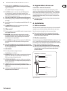
2.3 Effects section
List of all multi-effects processor presets.(35)
The LED level meter on the effects module should always show a sufficiently (36)
high level. Make sure that the Clip LED illuminates with signal peaks only. If it
is constantly illu-minated, the effects processor is overloading, which can
lead to unpleasant distortion. The FX SEND fader (PMP1000) or FX/FX 1/2
fader (PMP3000/PMP5000) controls the level sent to the effects module and
to the FX SEND output jacks.
The effects display always reads the currently selected preset.(37)
PMP3000/PMP5000: Press the (38) FX 1/2 IN switch to activate the
effects processor.
PMP1000/PMP3000: Turn the PROGRAM control to select an effects (39)
algorithm (preset number starts flashing). Press this control to activate the
effect selected (PMP5000: FX 1/2 (PUSH)).
PMP1000: The effects processor is operative all the time. Adjust the ◊
effect intensity for the MAIN or MON signals with controls (40) or
(42) respectively.
PMP5000: The PMP5000 has two separate effects processors, which can be
used independently of one another. Enable one or both processors with the
FX1/2 IN (38) buttons.
PMP3000/PMP5000: The (40) FX 1/2 TO MON 1 control allows you to set the
intensity of the multi-effects processors in the monitor mix. No effect is sent
to the monitor mix when this control is set fully counter-clockwise.
PMP1000: The FX TO MON control performs the same function as on the
PMP3000 and PMP5000.