


EURODESK SX3242FX/SX2442FX
Control elements and connections 9
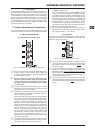
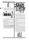
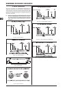
(37) The red “+48 V” LED illuminates when phantom power is on.
Phantom power is required for the operation of condenser
microphones, and can be switched on with the corresponding
switch on the rear of the console.
(38) The POWER LED is illuminated when the console is switched
on.
(39) The high-precision level meter accurately indicates the output
signal level. For example, when you press the SOLO switch
on one of the input channels, its signal level will be displayed
here, either pre-fader (PFL) or post-fader (SOLO), depending
on the position of the SOLO/PFL switch (see (40)). In PFL
mode only the left display is active, because the PFL signals
are mono.
(40) The SOLO/PFL switch determines whether the monitored
signal is pre (PFL) or post-fader (SOLO) after pressing the
SOLO/PFL switch (the LED illuminates). The level meter
indicates the corresponding signal (see (39)). When you
adjust a signal with the TRIM control, it is advisable to select
PFL mode, so that the level shown is independent of the
channel fader position.
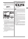
Talkback2.6.1
The talkback function of the EURODESK allows you to commu-
nicate with the musicians in the recording room or on the stage.
The talkback signal is present at the AUX SEND outputs, which
are particularly useful for monitor/headphone mixes.
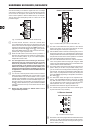
Talkback sectionFig. 2.17:
(41) The LEVEL control determines the volume of the talkback
signal at the AUX 1/2 outputs.
(42) Use the TALK TO AUX 1/2 switch to activate the built-in talk-
back microphone. Its signal is sent to the AUX SEND jacks
1 and 2. Keep the switch pressed while you’re speaking.
(43) This is the built-in talkback microphone.
Phones & control room2.6.2
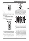
Phones/control room sectionFig. 2.18:
(44) The PHONES/CTRL R control adjusts the volume of the
headphones connected to the PHONES/CTRL ROOM OUT
jack (see (46)). If you have an active monitor speaker or
power amp connected here, you can also control the monitor
volume.
(45) These switches select the signal sent to the PHONES/CTRL
ROOM jack. Available sources are: MAIN, CD/TAPE, AUX
1/2 and subgroups 1 - 2 and 3 - 4.
Phones/control room outputFig. 2.19:
(46) Connect your headphones or monitor speaker to the
PHONES/CTRL ROOM OUT 1/4" TRS connector.
IMPORTANT! High volume levels may damage your +
hearing and/or your headphones/loudspeakers. To
avoid switch-on/off thumps from the console and any
downstream devices, always make sure that the power
amp(s) or active speaker(s) are the last components that
are switched on and the rst to be switched off. Always
make sure that the appropriate volume is set.
CD/tape2.7
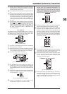
CD/tapeFig. 2.20:
(47) TO MAIN controls the volume of, for example, a CD player
connected to the CD/tape input connectors (see (49)).
(48) When the STANDBY switch is pressed, all input channels
are muted. Only the CD/tape signal will be routed to the
main mix. In this way, you can prevent the microphones from
pickung up unwanted sounds or noise that would interfere
with CD playback during a break. The main mix and chan-
nel faders can remain in their normal positions while playing
back music from CD (using the CD/TAPE INPUTs (49)), so
you don’t lose your mix.
CD/tape connectorsFig. 2.21:
(49) The CD/TAPE INPUT RCA connectors are for the connection
of CD players, tape decks or other line-level sources. The
signal volume is adjusted with the TO MAIN control.
(50) The CD/TAPE OUTPUT RCA connectors provide the stereo
main mix signal to a tape deck or DAT recorder to record
your mix. The signal is taken pre-fader, so that it will not be
inuenced by the fader positions.
Master aux send 1 and 22.8
Master aux sendsFig. 2.22:
(51) These are the master AUX SEND controls 1 and 2 for ad-
justing the volume level sent to the corresponding aux send
connectors (see (52)). This way, you can control the mix of
all AUX 1 or AUX 2 signals of the input channels. The AUX
SEND section also has a SOLO switch.