


8
U-CONTROL UMX49/UMX61
4. OPERATION
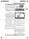
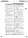
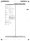
Fig. 3.1: TOP view of the UMX
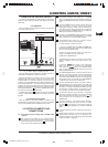
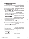
Fig. 3.2: Rear panel connectors
Use this socket to supply the UMX with current from an
external power supply unit (not included).
The USB connector of the UMX. The connector (type B) on
the device is connected using the cable supplied to a free
slot on the host computer (where you will find a type A
connector). It is compatible with the USB1.1 and/or USB2.0
standards.
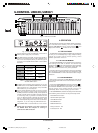
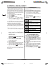
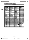
Operation Octave shift LED
press once
Shift one octave
up or dow n
LED on
press 2nd
time
Shift 2 octaves
up or dow n
flashing
press 3rd
time
Shift 3 octaves
up or dow n
flashing
press both
buttons
Reset (all octave
shifts are reversed)
LED off
Table 3.1: LED activity depending on the
OCTAVE SHIFT status
In addition to the connection to the computer, you can use
the MIDI OUT to connect additional MIDI devices, so that the
UMX transforms into a fully-featured, easily accessible
MIDI interface for your host computer.
Use the FOOT SWITCH connector to connect a sustain
pedal. This interface is factory preset and assigned to
the MIDI parameter “Foot Pedal” (CC 64), which represents
a switch controller. When the pedal is pressed (and held)
in normal Play mode, it generates a controller with the
value 127. When the pedal is released, the controller falls
back to 0 (typical piano sustain pedal behavior). Apart
from that the pedal assignment is the same as the button
assignment, i.e. you can assign any MIDI controller to it.
The POWER switch is used to switch the unit on and off.
Please close all programs if you want to switch off
the UMX25 while the computer is running or
terminate the USB connection.
4. OPERATION
We will explain the operation of the UMX in detail in the following.
You must observe the following: There is a differentiation
between push-buttons (refer to control elements ) and
keys (control element )! Please do not confuse these!
4.1 THE PLAY MODE
The UMX will be in the Play Mode immediately after it is switched
on. Here you can immediately begin to play, modify the filtering
process via the rotary controls, execute panning, control
software synthesizers and so on...
4.1.1 THE FACTORY MEMORY
The FACTORY MEMORY is the installed memory in which the
basic settings of the UMX are defined. The controller map
described under is the most important item of the FACTORY
MEMORY. These settings are automatically loaded after each
start of the device and control many useful parameters.
Instructions which are changed within a session are discarded
when the device is switched off. We have equipped the UMX
with a USER MEMORY, in order to still be able to store changed
allocations.
4.1.2 THE USER MEMORY
Settings which are stored in the USER MEMORY remain stored
in the internal Flash ROM and are retained after the device is
switched off.
Change to the USER MEMORY by pressing push-button . If
you call up the USER MEMORY for the first time, the settings of
the FACTORY MEMORY will be used initially. As soon as you
execute changes in the existing controller map, they are
automatically stored - without requiring any further action.
In the USER MEMORY, allocations including channel information
of the following control elements can be permanently stored:
- FOOT SWITCH connection
- OCTAVE SHIFT push-button
- VOLUME/DATA fader
- PITCH BEND wheel
- MODULATION wheel
- Rotary controls R1 - R8
- Push-buttons B1 - B8
DATA-MANFULL_UMX49_ENG_Rev_A.pmd 12.01.2006, 20:368