


5
ULTRAVOICE DIGITAL VX2496
2. CONTROL ELEMENTS
Once you have developed a feel for the individual components,
you can unleash your creativity by combining individual functions.
+ This manual first describes the terminology used,
so that you fully understand the VX2496 and its
functions. Please read the manual carefully and keep
it for future reference.
1.1 Before you get started
Your ULTRAVOICE DIGITAL was carefully packed in the
factory, and the packaging is designed to protect the unit from
rough handling. Nevertheless, we recommend that you carefully
examine the packaging and its contents for any signs of physical
damage, which may have occurred during transit.
+ If the unit is damaged, please do NOT return it to
BEHRINGER, but notify your dealer and the shipping
company immediately. Otherwise, claims for damage
or replacement may not be granted.
Be sure that there is enough space around the unit for cooling
and, to avoid overheating, please do not place your
ULTRAVOICE DIGITAL on power amplifiers, etc.
The mains connection is via the enclosed power cord and a
standard IEC receptacle. It meets all international safety
certification requirements.
+ Please make sure that all units have a proper
ground connection. For your own safety, never
remove or disable the ground conductor from the
unit or the AC power cord.
Before you connect your ULTRAVOICE DIGITAL to the
mains, please make sure that the voltage setting on
your unit matches the local voltage! The fuse holder above
the AC power connector has 3 triangular markings. Two of
these three triangles are aligned with one another. The VX2496
is set to the voltage shown next to these markings and can be
switched over by turning the fuse holder by 180°. IMPORTANT:
This does not apply to export models designed exclusively
for 120 V operation!
2. CONTROL ELEMENTS
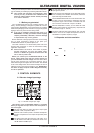
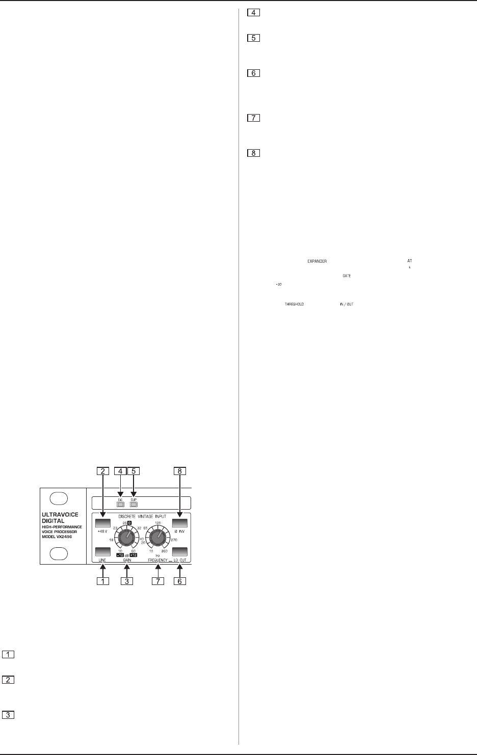
2.1 Discrete vintage input stage
Fig. 2.1: Discrete Vintage input stage
This section of the ULTRAVOICE DIGITAL is a preamp
where you regulate the input level of the microphone or
line level signal.
Use the LINE button to select the type of input signal
(pressed = LINE, not pressed = MIC).
Press the +48 V button to power a condenser microphone.
Dynamic microphones do not require this phantom power
supply.
The GAIN control sets the input level. The scale -12 to
+12dB relates to the LINE input whereas the scale +10 to
+60dB relates to the MIC input.
The SIG LED above the gain control illuminates when an
input signal is present.
Ensure that the CLIP LED lights up only with peak signals.
If it is constantly lit or if distortion can be heard, reduce the
input level using the GAIN control.
The ULTRAVOICE DIGITAL has a low-cut filter which can
be used to remove low-frequency interference from the
microphone signal. This function is activated with the
LOCUT button. This filter has a slope of 12 dB/oct.
With the FREQUENCY control, you can select the cutoff
frequency below which the low-frequency component will
be removed (range 15 - 360 Hz).
The Ø INV shifts the input signal phase by 180°. Use this
function if the use of multiple microphones results in
cancellations of specific frequency ranges.
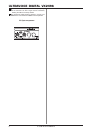
2.2 Expander and tube emulation