


17 XENYX XL1600/XL2400/XL3200 User Manual
behringer.com
MON
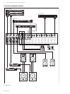
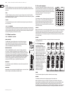
A signal sent from AUX RETURN can be added to the stage mix using the
MON control.
AUX RETURN
The AUX RETURN controls adjust the volume level of the aux return signals in the
main mix.
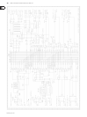
Modications6.
These modifications require soldering. Attempt only if you are ◊
experienced in using an iron on PCBs. Otherwise, refer to qualified
personnel. After modification the warranty becomes void.
We wish to be absolutely clear that BEHRINGER cannot be held ◊
responsible after you start disassembling your XENYX. If you make
much of your warranty privileges, think again.
Links should not be threaded into the holes on the PCB, but are to ◊
be soldered to the tinned areas around the holes. Bend the links a
little upwards.
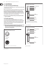
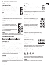
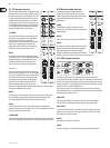
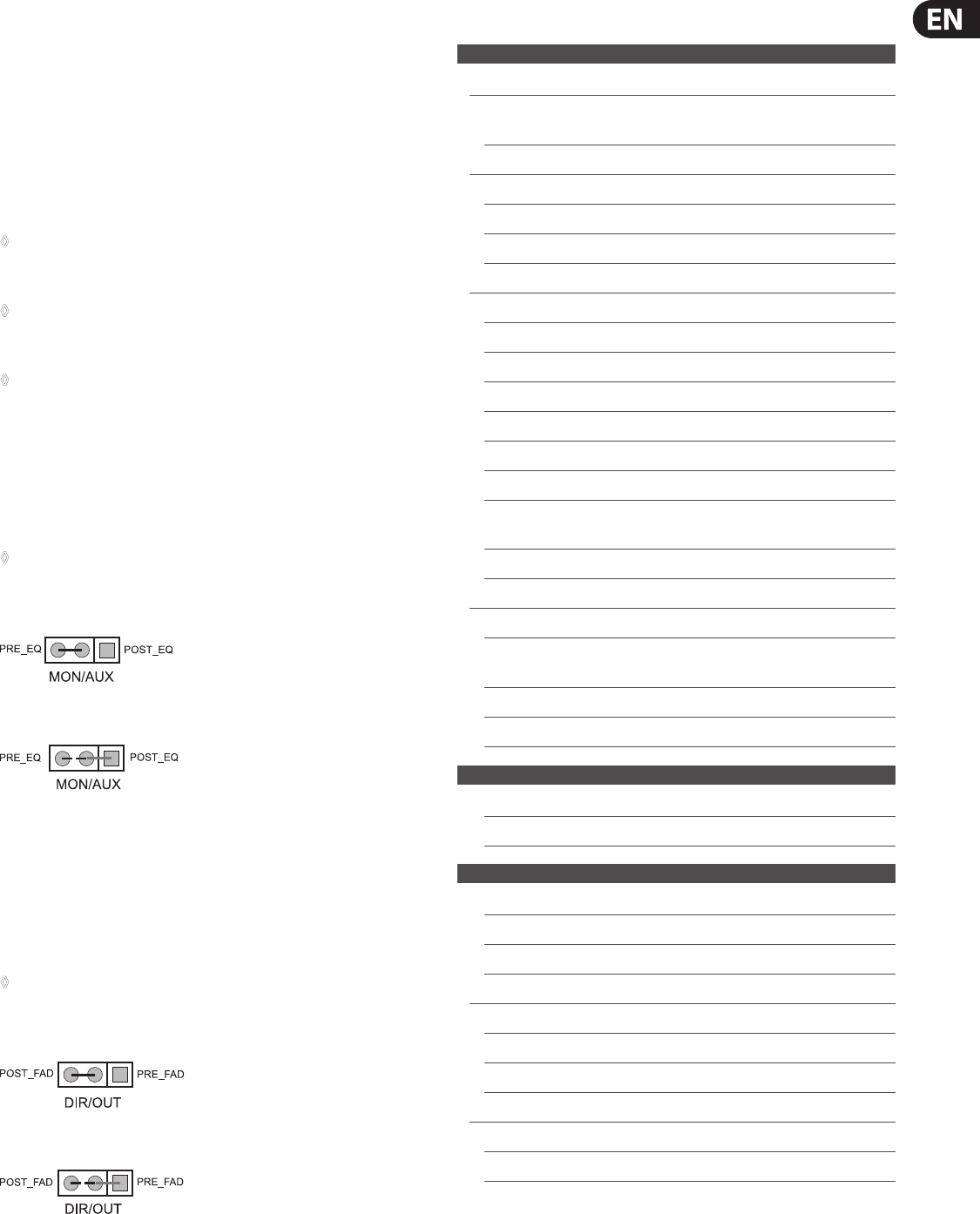
Mon/Aux sends > post-EQ6.1
Pre-fader switched monitor sends and aux sends are tapped o before the
equalizer. Do you prefer post-EQ? What are you waiting for? You don't have to
look far—the necessary information is found on the bottom side of the unit.
Make sure to turn off the mixer and disconnect it from the mains before ◊
removing the cover.
Strip the PRE EQ lead.1)
Solder a POST EQ link into place.2)
Make these modications to as many channels as required (does it have to be 3)
all of them?).
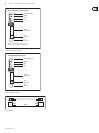
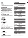
Direct Out > pre-fader6.2
If you prefer to use the Direct Out pre-fader than post-fader, the signal needs
to be tapped o before the fader and not after the fader. To perform this
modication, nd the label "DIR-OUT" on the circuit board.
Make sure to turn off the mixer and disconnect it from the mains before ◊
removing the cover.
Strip the POST FADER lead.1)
Solder a PRE FADER link into place.2)
Make these modications to as many channels as required.3)
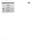
Specications7.
Mono inputs
Microphone inputs (XENYX Mic preamp)
Type XLR connector, electronically balanced,
discrete input circuit RF rejection lters
Mic E.I.N.
1
(20 Hz - 20 kHz)
@ 0 Ω source resistance -127 dB / 129.7 dB A-weighted
@ 50 Ω source resistance -126 dB / 128.3 dB A-weighted
@ 150 Ω source resistance -125 dB / 126.5 dB A-weighted
Frequency response
To Direct Out <10 Hz - 50 kHz (-1 dB)
<10 Hz - 100 kHz (-3 dB)
To Insert Send <10 Hz - 90 kHz (-1 dB)
<10 Hz - 170 kHz (-3 dB)
Gain range 0 dB to +60 dB
Max. input level +24 dBu @ 0 dB Gain
Impedance approx. 2.6 kΩ balanced
Signal-to-noise ratio 120 dB / 122 dB A-weighted
(0 dBu In @ +22 dB Gain)
Distortion (THD + N) typ. 0.0008 %
Line input
Type ¼" TRS jack, electronically balanced
Impedance approx. 20 kΩ balanced,
approx. 10 kΩ unbalanced
Gain range -10 dB to +40 dB
Max. input level +22 dBu @ 0 dB Gain
Channel inserts
Type ¼" TRS jack, unbalanced
Max. input level +22 dBu
Channel direct outs
Type ¼" TRS jack, balanced
Impedance approx. 75 Ω balanced
Max. input level +22 dBu
Crosstalk
2
Main fader closed 100 dB
Channel muted 90 dB
Channel fader muted 85 dB
Frequency response (Mic In → Main Out)
<20 Hz - 20 kHz +0 dB / -1 dB
<10 Hz - 160 kHz +0 dB / -3 dB
1) Equivalent Input Noise
2) Measuring conditions: 1 kHz rel. to 0 dBu; 20 Hz - 20 kHz; line input; main output; unity gain