


ULTRAZONE ZMX8210
Controls and connectors6
In stereo mode (switch not pressed), the signal of the =
L input is sent to the LEFT bus, the R input is sent to
the RIGHT bus and a mixed L/R signal is sent to the
AUX bus.
LEDs: These have the same function as the control {8} {6}. In
stereo mode, the LEDs show the summed level of the input
signals L and R.
LEVEL: This has the same function as the control {9} {5}. In
stereo mode, the control adjusts the volume level of the
L/R signal.
CH SELECT: This switch is used either to activate channel [10]
7 or 8. The active channel is indicated by the glowing of the
corresponding LED.
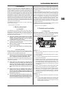
Controls of the ZMX8210Fig. 2.2:
Main section
MIC LOW CUT: This switch cuts low-frequency rumble [11]
below 100 Hz
MIC MIX: This switch removes the signal of channels 1 – 6 from [12]
the remote control function, allowing only the output volume of
channels 7/8 on the LEFT/RIGHT bus to be remote controlled.
When the switch is not pressed, the total volume of all chan-
nels fed to the LEFT/RIGHT bus are remote controlled.
RIGHT MUTE: This switch excludes the RIGHT bus from [13]
the Mute function. This is helpful when using the RIGHT and
LEFT buses for different zones (rooms).
When the switch is pressed, the signal of channels 1 – 8, =
which is dependent on the signal level of channel 1, is
muted on both the LEFT and RIGHT bus. This occurs
when the input level of channel 1 drops below the speci-
ed threshold value (THRESH {4}).
When the switch is not pressed, only the LEFT bus =
is muted while the RIGHT bus continues to transmit
a signal, provided the individual channels have been
routed accordingly.
EQ ON: The switch activates the equalizer [14] [15] for the LEFT
and RIGHT bus.
LOW/LOW MID/HIGH MID/HIGH: This knob adjusts the [15]
boost/cut of factory-preset frequencies as follows:
LOW: This boosts/cuts frequencies below 70 Hz by a =
maximum of ±15 dB.
LOW MID: This boosts/cuts frequencies around 300 Hz =
by a maximum of ±15 dB.
HIGH MID: This boosts/cuts frequencies around 3 kHz =
by a maximum of ±15 dB.
HIGH: This boosts/cuts frequencies above 10 kHz by a =
maximum of ±15 dB.
Buses
LEDs: When the CLIP LED lights up, attenuate the output [16]
level by using the LEVEL knob [17] to avoid clipping.
LEVEL: This knob adjusts the output level of the bus outputs [17]
OUT L, OUT R and AUX.
Mains
POWER: The POWER switch powers up the mixer. The [18]
POWER switch should be in the Off position when connecting
the unit to the mains.
To disconnect the unit from the mains, please pull the +
mains plug. When using the unit, make sure that the
mains plug is readily accessible. When using the unit
mounted in a rack, please make sure that you can easily
disconnect the unit from the mains by using a plug or a
circuit breaker on the backside.
Please note: The POWER switch does not entirely dis- +
connect the unit from the mains when turned off. For
this reason, disconnect the cable from the mains plug
when the unit is not used for a long period.
SERIAL NUMBER: The serial number is found on the rear panel.
It is required for online registration.
Rear panel2.2
The BUS LINKS connector as well as the channel inputs 7 and 8
are unbalanced. The other PCB inputs and outputs are balanced.
To use balanced connectors for unbalanced connections, insert
a jumper wire between the ground pin (m) and the negative pin
(-).
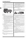
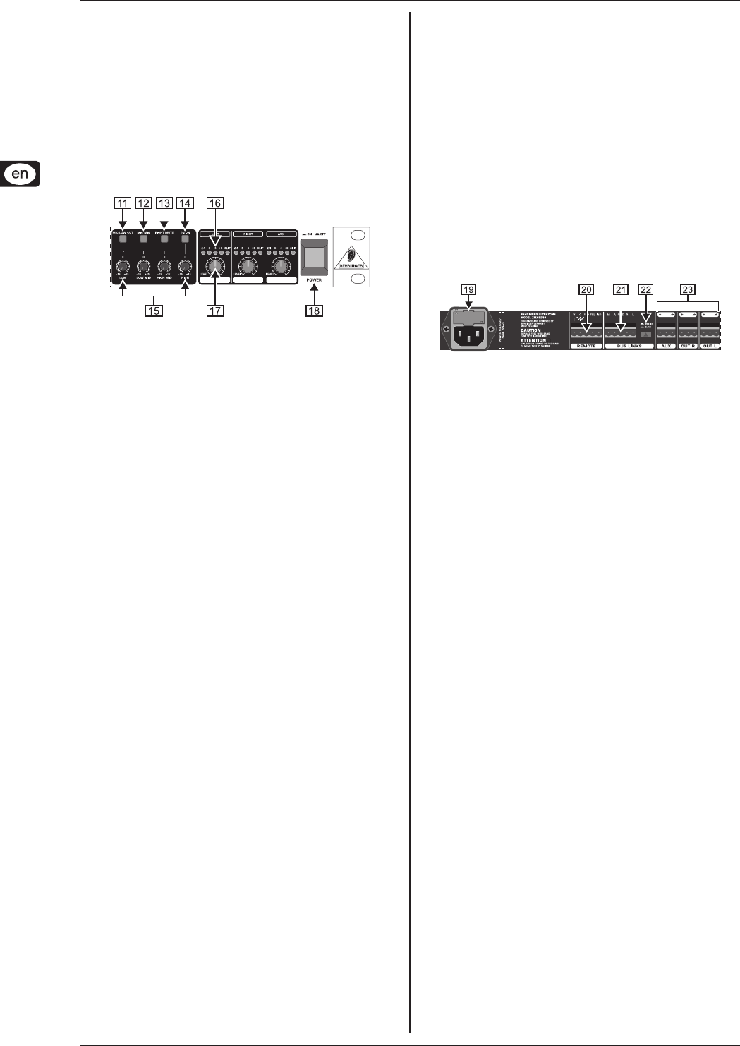
Connections of the ZMX8210Fig. 2.3:
FUSEHOLDER/IEC power receptacle: The connection to the [19]
mains is established through an IEC connector. It meets all
of the international safety certication requirements. A tting
power cord is included. When replacing the fuse, you need
to use the same type.
Before you change the fuse, switch off the device and +
pull the plug to avoid electric shock or damage to the
device.
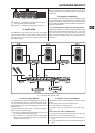
REMOTE: This connector is used for connecting components [20]
to remote control the ZMX8210.
It is possible to connect a simple potentiometer to remote =
control the volume of the LEFT and RIGHT buses (see
Chapter 3.1.3).
Connect a push-button switch and two control diodes to =
remote control the CH SELECT switch {10} of channels
7 and 8 (see Chapter 3.1.3).
BUS LINKS: Use this connector to link two ZMX8210s [21]
together to provide additional inputs (signals). The three
output buses LEFT/RIGHT/AUX are linked together using
the connector. The mute signal of the ZMX8210 which is set
to be the master is also transmitted so that the mute function
of the master is also able to mute the buses of the slave.
SLAVE/MASTER: The switch places the ZMX8210 in the [22]
master or slave mode of operation.
When the switch
is pressed, the ZMX8210 is placed in the slave mode =
of operation.
is not pressed, the ZMX8210 is placed in the master =
mode of operation.
The ZMX8210 needs to be used in master mode when +
no additional units are connected!
When more than one ZMX8210 are connected, only one +
unit is allowed to be in master mode. The other units
need to be placed in the slave mode of operation.
AUX/OUT R/OUT L: Balanced signal outputs for buses AUX, [23]
RIGHT and LEFT.