


ULTRAZONE ZMX8210
Installation 9
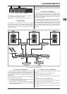
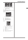
Pin assignment of the output bus connectorsFig. 4.2:
+: Signal (positive / balanced)
-: Signal (negative / balanced)
m: Ground
Use all three pins for a balanced connection.
For an unbalanced connection, use pins m and + and insert a
jumper wire between pins m and -.
BUS LINKS
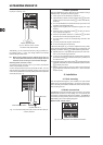
Pin assignment of the BUS LINKS connectorFig. 4.3:
M: M(UTE) bus signal link
A: A(UX) bus signal link (unbalanced)
SHD: SH(IEL)D signal link (shield)
R: R(IGHT) bus signal link (unbalanced)
L: L(EFT) bus signal link (unbalanced)
REMOTE
Pin assignment of the REMOTE connectorFig. 4.4:
V: V(OLUME) connection to the potentiometer
(potential)
C: C(ONTROL) connection to the potentiometer
(mid tap)
SHD: SH(IEL)D connection
(shield)
SEL: SEL(ECT) connection to the push-button switch
IND: IND(ICATOR) connection to the LEDs