


14
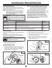
Reinstalling the Air Filter/Muffler Cover
1. Place the air filter/muffler cover over the back of the
carburetor and muffler. Align the screw holes.
2. Insert the four (4) screws into the holes in the air
filter/muffler cover (Fig. 21) and tighten.
Do not over tighten.
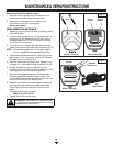
SPARK ARRESTOR MAINTENANCE
1. Remove air filter/muffler cover. Refer to Removing the Air
Filter/Muffler Cover.
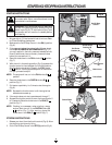
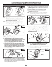
2. Locate muffler front and the two (2) bolts securing it to
the engine (Fig. 24). Remove the two (2) bolts using a
flatblade screwdriver or 5/16-inch socket or nut driver.
Pull muffler off of the engine.
3. Turn muffler over to the back side and locate the exhaust
gasket. Remove the muffler gasket from the muffler (Fig. 24).
NOTE: If the exhaust gasket is torn or damaged, replace
it with a new gasket before reassembling muffler.
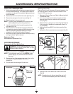
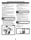
4. Using a small flatblade screwdriver, carefully pry up the
spark arrestor from the recessed hole (Fig. 25). Remove
the spark arrestor from the muffler.
5. Clean the spark arrestor with a wire brush. Replace it if it is
damaged or if it is impossible to clean thoroughly (Fig. 25).
6. Reinstall the spark arrestor by pressing it into the
recessed hole on the muffler's back side. Make sure it fits
tightly against the muffler and is not raised up.
7. Place the exhaust gasket against muffler's back side.
Align the gasket bolt holes with the bolt holes in the
muffler. While holding exhaust gasket in place, insert the
bolts into the muffler's front side (Fig. 24).
8. Place the muffler (with the exhaust gasket in place and
bolts inserted), against the engine, aligning the bolt
holes. Tighten the bolts to secure the muffler to the
engine.
If using a torque wrench, torque to:
80-90 in.•lb. (9-10.2 N•m)
9. Reinstall the air filter/muffler cover.
Muffler - Front Side
Muffler - Back Side
Bolts
Exhaust
Gasket
Spark
Arrestor
Muffler - Back Side
Spark
Arrestor
Flatblade
Screwdriver
Spark Arrestor
WARNING:
If the muffler is not tightened secure-
ly, it could fall off causing damage to the unit and
possible serious personal injury
MAINTENANCE & REPAIR INSTRUCTIONS
Fig. 25
Fig. 24