


Configuration
Call Station DIP switch settings, page 23
Wall Control Panel DIP switch settings, page 24
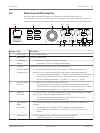
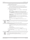
Multi Channel DSP Amplifier settings, page 25
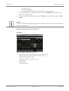
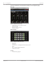
DSP matrix mixer PC GUI, page 26
Multi Channel DSP Amplifier PC GUI, page 28
Call Station
Configuration of zone groups, printable labels for the call stations and chimes is done via the
PC software GUI. Refer to DSP matrix mixer PC GUI, page 26.
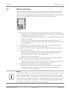
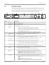
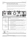
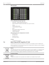
Call Station DIP switch settings
DIP switches are use to set individual ID numbers to the call stations. This is so it can be
recognized by the DSP matrix mixer in the system. Each connected call station must have its
own individual ID assigned.
1. To set the call-station ID use the 3‑way DIP switch on the base of the unit:
– Factory default ID setting: call station 1 (all switches are OFF).
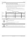
Call station ID numbers
DIP switch 1* 2 3 4 5 6 7 8
1 OFF ON OFF ON OFF ON OFF ON
2 OFF OFF ON ON OFF OFF ON ON
3 OFF OFF OFF OFF ON ON ON ON
* Factory default.
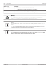
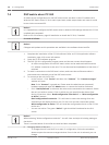
Notice!
A DIP switch in the down position is OFF.
A DIP switch in the up position is ON.
Eg. Down – Up - Down will equal call station ID number 3 in the table above.
7
7.1
7.1.1
PLENA matrix Configuration | en 23
Bosch Security Systems B.V. Operation manual 2013-06 | V1.0 |