


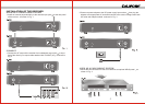

1.POWER SWITCH AND VOLUME CONTROL
Turn the knob clockwise until it clicks to switch on the power. Further turning will
increase the volume.
2.POWER ON INDICATOR
When power is switched on the power on LED will light up.
3.RF SIGNAL INDICATOR
Indicates RF signal received. As soon as signal is emitted from the microphone
the LED of the indicator will light up.
4.AF SIGNAL INDICATOR
Indicates the audio signal. When sound is applied to microphone LED will light
up.
5.ANTENNA INPUT JACK
For direct mounting of antenna or antenna extension cable.
6.UNBALANCED AUDIO OUTPUT JACK
7.DC POWER SUPPLY INPUT SOCKET
A 12-15V external DC power supply or an AC adapter could be connected to this
socket while the negative is grounded.
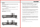
CONTROLS AND FUNCTIONS
The overall system is a combination of a receiver and a wireless microphone. The
combination for R-1000 or R-2000 could be selected as the following.
BASIC COMBINATION SYSTEM
R-1000 / R-2000 matches Q-1000 M-1000
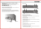
BASIC COMBINATION SYSTEM
When two or more wireless microphone are used carriers must be different from
the others in order to avoid mutual interference.
To make sure that the system performs correctly please place the receiver at
least 1 meter above the ground and at least 1 meter away from concrete walls or
metal surfaces to prevent any reflection. The microphone should also be at least 1
meter away from the receiving antenna as shown in Fig. 5.
USED AS MULTI-CHANNEL SYSTEM
INSTALLATION OF THE SYSTEM
REAR PANEL
OPERATION INSTRUCTIONS OF OVERALL SYSTEM
R