


— 4 —
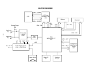
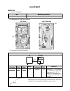
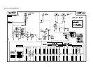
CPU (LSI1: MSM6755C-17)
The CPU reads sound data from the ROM in accordance with the pressed key and the selected tone; the CPU
can read rhythm data simultaneously when a rhythm pattern is selected. Then it provides the left and the right
channels’ waveforms separately, by converting the data into the waveforms with two built-in DACs. The CPU
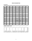
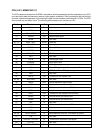
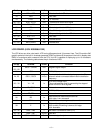
also controls key and button input. The following table shows the pin functions of LSI1.
Pin No. Terminal In/Out Function
1 MA14 Out Address bus
2, 3 NCO — Not used
4 ~ 19 MA0 ~ MA13 Out Address bus
13 MRDB Out Read enable signal
17 MCSB — Not used
20 ~ 27 MD0 ~ MD7 In/Out Data bus
28, 29 NC1, NC2 — Not used
30 DGND In Ground (0 V) source
31 DVCC In +5 V source
32, 33 XTLO, XTLI In/Out 20 MHz clock input/output
34 NC3 — Not used
35 RSTB In Reset signal input
36 P24/RXD — MIDI signal input
37 P25/TXD — MIDI signal output
38 NMI In Power ON signal input. Connected to +5 V.
39 APO Out APO (Auto Power Off) signal output
40 NC4 — Not used
41 REFH Out Terminal for the internal DAC
42, 43 NC5, NC6 — Not used
44 DAOR Out Sound waveform signal output
45 NC7 — Not used
46 AVdac In +5 V source for the internal DAC
47 DAOL Out Left channel sound waveform output
48 REFL Out Terminal for the internal DAC and ADC
49 AGdac In Ground source for internal DAC
50 AGadc In Ground source for internal ADC
51 ANI In Not used
52 AVadc In +5 V source for the internal ADC
53 NC8 — Not used
54 MOD0 In Mode selection terminal. Connected to +5 V.
55, 56 MOD1, MOD2 In Mode selection terminal. Connected to ground.
57 P40 — Not used
58 ~ 64 KI0/P30 ~ KI7/P36 In Terminals for key/button input signal
65 KI7/P37 — Not used
66 ~ 73 KO0/P50 ~ KO7/P57 Out Terminals for key scan signal