


8
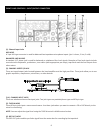
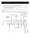
FRONT PANEL CONTROLS – MAIN CONTROL SECTION
(1). PHANTOM POWER INDICATOR
This indicator lights when the phantom power switch is turned on.
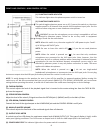
(2). PHANTOM POWER SWITCH
This switch toggles phantom power on or off. If you set the switch on, the mixer
supplies power to all channels that provide XLR microphone input jacks. Set this
switch on when using one or more condenser microphones.
WARNING, be sure the microphone you are using is compatible or will not
be affected by phantom power. Failure to do so may result in equipment
damage. Please see the notes below:
NOTE: When this switch is on, the mixer supplies DC +48V power to pins 2 and 3
of all XLR-type MIC INPUT jacks.
NOTE: Be sure to leave this switch off ( ) if you do not need phantom
power.
NOTE: When the switch is pressed on ( ), be sure that only condenser
microphones are connected to the XLR input jacks. Note, however, that the
switch may be left on without problem when connecting to balanced dynamic
microphones. Be sure the balanced dynamic microphone you are using is not
affected by phantom power in any way before connection is made. The same
applies with ribbon microphones.
NOTE: When the switch is pressed on ( ), do not use single-ended
(unbalanced) microphones or instruments into the XLR input jacks. Do not plug
instrument outputs into the XLR input jack unless you know for certain it is safe to do so.
NOTE: To avoid damage to the speakers, be sure to turn off the amplifier (or powered speakers) before turning this
switch on or off. We also recommend that you turn all controls (MAIN L/R, CTRL ROOM / HEADPHONE, etc) to minimum
settings before operating the switch, to avoid risk of loud noises that could cause hearing loss or device damage.
(3). TAPE IN CONTROL
This control adjusts the level of the playback signal that is inserted to the master mixing bus from the TAPE IN RCA
jacks on the top panel.
(4). STEREO RETURN CONTROL
Adjust the level of the mixed L/R signal sent from the RETURN jack (L (MONO) and R) to the Main L/R bus.
(5). CTRL ROOM /PHONES CONTROL
Controls the level of the signal output to the HEADPHONE jack and the CONTROL ROOM L and R jacks.
(6). MAIN L/R MASTER VOLUME
This volume adjusts the final level of the combined signals from all channels.
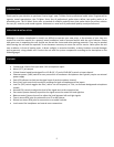
(7). OUTPUT LEVEL METER
A vertical row of ten LED shows the continuous output level of MAIN OUTPUT L/R. This type of display is highly visible
under poor lighting conditions. The 0 LED means an output level of +4dB for +4dB output (that’s the rated level).
(8). POWER INDICATOR This indicator lights when the power switch is turned on.