


GFX50 TwoTone Guitar Amplifier with DSP
1 2 4 5 6 7 8 10 11 12 14 16151393
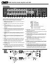
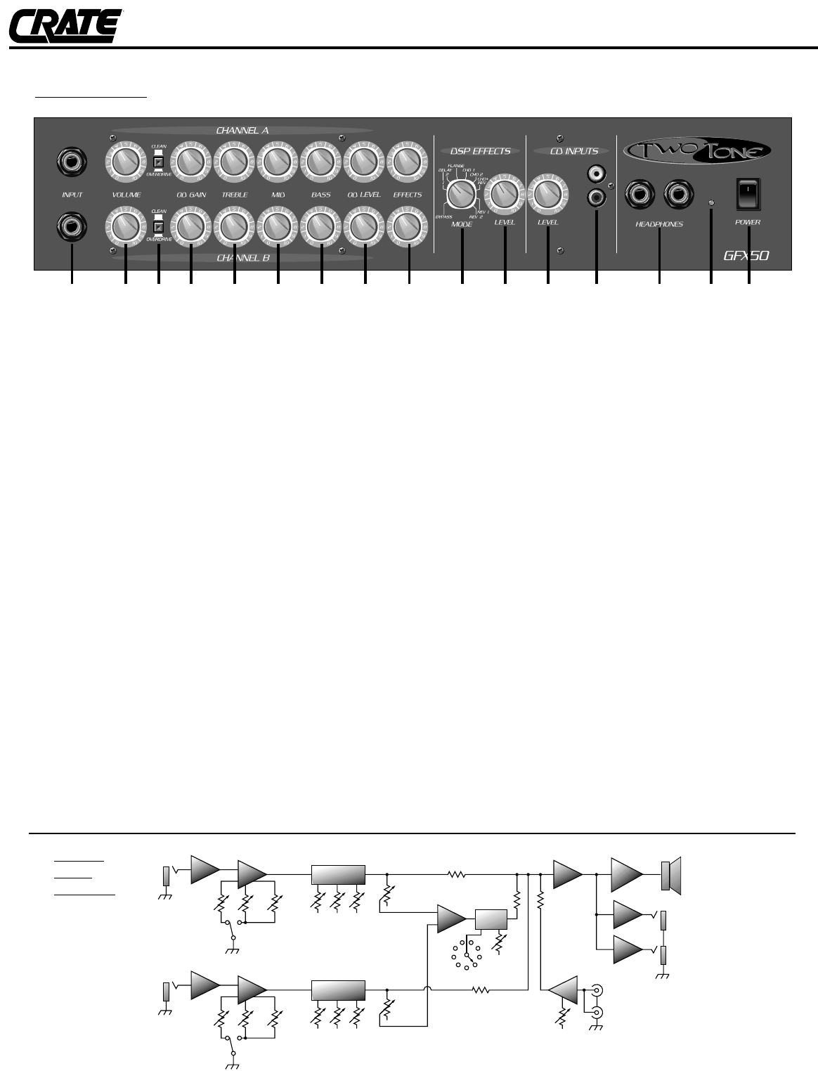
The Front Panel:
Channel A and B are independent of each other up to the DSP and
CD inputs. The text below (#1–9) applies to both channels.
1. INPUT: Connect the output signal from your guitar here by means of
a shielded instrument cable.
2. VOLUME: Use this control to set the clean channel’s output signal
level.
3. CLEAN/OVERDRIVE: Use this switch to select the clean channel
(switch in the out position) or the overdrive channel (switch
depressed).
4. OD GAIN: Use this control to set the overdrive channel’s input sig-
nal gain. This control works in conjunction with the level control (#8)
to set the amount of distortion and the output signal level of the
overdrive channel.
5. TREBLE: Use this control to adjust the high frequency level of the
output signal. This control has a range of 27dB of boost or cut at
12kHz.
6. MID: Use this control to adjust the midrange frequency level of the
output signal. This control has a range of 20dB of boost or cut at
1.5kHz.
7. BASS: Use this control to adjust the low frequency level of the out-
put signal. This control has a range of 28dB of boost or cut at 40Hz.
8. OD LEVEL: Use this control to set the overdrive channel’s output
signal level. (Works in conjunction with the gain control, #4.)
9. EFFECTS: Use this control to set the amount of DSP effects applied
to the output signal.
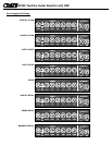
10. DSP MODE: Use this control to select the type of digital signal pro-
cessing effect(s) applied to the output signal. Each effect and its
location is called out by the markings around the control. The effects
are as described as follows:
BYPASS: No effect
DELAY 1: Short delay effect
DELAY 2: Long delay effect
FLANGE: Light flanging effect
CHO 1: Slow chorus effect
CHO 2: Fast chorus effect
CHO+REV: Slow chorus effect with reverberation
REV 1: Small room reverberation
REV 2: Large hall reverberation
11. DSP LEVEL: Use this control to set the amount of digital effect
applied to the output signal.
12: CD INPUTS LEVEL: Use this control to adjust the level of the signal
applied to the the CD input jacks (#13).
13. CD INPUT JACKS: Use these jacks to connect the output of a CD
or tape player to the amp. (The jacks are internally summed to cre-
ate a mono signal.)
14. HEADPHONES: Use these jacks to connect one or two pairs of
stereo headphones to the amplifier. When the headphones are
used, the internal speaker is disconnected.
15. LED: This LED illuminates when the amplifier is on.
16. POWER: Use this switch to turn the amplifier on and off. The ampli-
fier is on when the top of the switch is depressed; off when the bot-
tom of the switch is depressed.
17. AC LINE CORD(rear panel, not shown): Plug this cord into a prop-
erly wired, grounded, 120 volt, 60 cycle AC outlet. DO NOT attempt
to defeat the ground connection of this power cord! If your ampli-
fier was purchased outside of the United States, see the unit’s rear
panel labeling for its power rating, and follow the above guidelines.
INPUT
OVER-
DRIVE
CLEAN
OD
GAIN
VOLUME
POWER
AMP
SPEAKER
CD
INPUTS
TREBLE MID BASS
EFFECTS
OD
LEVEL
OD
GAIN
OD
LEVEL
LEVEL
LEVEL
MODE
DSP
MIX
STAGE
HEAD
PHONES
CHANNEL A:
INPUT
OVER-
DRIVE
CLEAN
VOLUME
TREBLE MID BASS
EFFECTS
CHANNEL B:
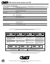
System
Block
Diagram: