


4
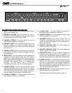
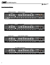
The Front Panel Controls and Their Use:
1. INPUT: This jack accepts a high impedance signal from a
guitar, bass, keyboard, etc.
2. CHANNEL A VOLUME: This control sets the level of
Channel A. The sound is brighter at lower settings, and can
be cranked up for a crunchy rhythm sound.
3. CHANNEL A TREBLE: This control adjusts the level of
high frequency response on Channel A.
4. CHANNEL A BASS: This control adjusts the level of low
frequency response on Channel A. (When playing at
extreme volume levels, you might want to back this control
down just a bit.)
5. CHANNEL SELECT: Silent channel switching is achieved
with this button. When the footswitch is plugged in, this but-
ton is deactivated.
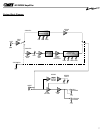
6. INSERT JACK: This jack provides a line level access point
between the preamp and the power amp. The output is
buffered by a single transistor. It is out of the circuit com-
pletely when nothing is plugged into it. Use a Crate Model
#CYC6MS mono-to-stereo Y-cord, or a Y-adapter with
extenders. For more details refer to the section
“Connecting to the Insert Jack” on the following page.
7. CHANNEL B GAIN: Use this control to achieve sounds
ranging from bluesy crunch to full tilt-hard rock rhythm.
Experimenting with a combination of the gain and volume
controls on the amp along with your guitar’s volume con-
trols can produce a wide variety of useable sounds.
8. CHANNEL B TREBLE: This control adjusts the level of the
high frequency response on Channel B.
9. CHANNEL B MID: This control adjusts the amount of
midrange frequency response on Channel B.
10. CHANNEL B BASS: This control adjusts the level of low
frequency response on Channel B.
11. CHANNEL B LEVEL: The overall volume level of
Channel B is controlled with this knob. When set at 2
o’clock, the power amp begins to be overdriven for true
power amp distortion.
12. CHANNEL A REVERB LEVEL: This control adjusts the
amount of reverb on Channel A.
13. CHANNEL B REVERB LEVEL: This control adjusts the
amount of reverb on Channel B.
14. FOOTSWITCH JACK: Use the supplied single-button
footswitch (Crate model #CFP-1) or an equivalent to
achieve silent remote channel switching. Plugging in the
footswitch deactivates the front panel channel switch (#5).
15. STANDBY SWITCH: This switch should remain turned off
when the unit is first turned on in order to allow the tubes
to warm up properly before high voltage is applied to
them. The Standby switch should also be turned off dur-
ing extended breaks in playing when the amp is left on.
This will help ensure longer tube life.
16. POWER SWITCH: This switch applies power to the unit
when switched to the on (up) position.
The Standby and Power switches light up when on.
1 2 3 4 6 7 8 10 11 12 13 14 15 1659
GT-500H Amplifier