


vii
Contents
Chapter 1 General Information ........................................2
1.1 Introduction ....................................................................... 2
1.2 Features ............................................................................. 3
1.3 Specifications .................................................................... 3
1.3.1 Standard SBC Functions................................................. 3
1.3.2 Display Interface............................................................. 4
1.3.3 Solid State disk ............................................................... 4
1.3.4 Ethernet interface............................................................ 4
1.3.5 Mechanical and Environmental ...................................... 4
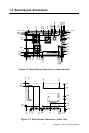
1.4 Board layout: dimensions.................................................. 5
Chapter 2 Installation ........................................................8
2.1 Jumpers.............................................................................. 8
Table 2.1:Jumpers........................................................... 8
2.2 Connectors......................................................................... 9
Table 2.2:Connectors...................................................... 9
2.3 Locating Connectors (component side)........................... 10
2.4 Locating Connectors (solder side)................................... 10
2.5 Setting Jumpers ............................................................... 11
2.6 Clear CMOS (J1)............................................................. 12
2.7 COM2 RS-232/422/485 Select (J2) ............................... .13
2.8 LVDS Panel Power Select (JP1)..................................... 13
2.9 Installing SODIMMs...................................................... .14
2.10 ATX power Connector (CN5)......................................... 14
2.11 Printer port Connector (CN4).......................................... 15
2.12 CompactFlash Socket...................................................... 15
2.12.1 CompactFlash (CN22) .................................................. 15
2.13 Floppy Connector (CN3)................................................. 16
2.13.1 Connecting the floppy drive ......................................... 16
2.14 IDE Connector (CN2) ..................................................... 17
2.14.1 Connecting the hard drive............................................. 17
2.15 VGA/LVDS interface connections.................................. 18
2.15.1 CRT display Connector (CN10) ................................... 18
2.15.2 LVDS LCD panel Connector (CN8) ............................ 18
2.15.3 LCD Inverter Connector (CN6).................................... 18
2.16 USB Connectors (CN9,CN11)........................................ 19
2.17 Ethernet configuration..................................................... 19
2.17.1 LAN Connector (CN13) ............................................... 19
2.17.2 Network boot ................................................................ 19
2.18 HDD LED/Reset/Power Button (CN1)........................... 20