


Master Section
3
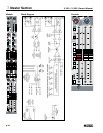
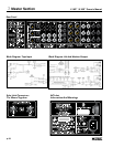
Rear Panel Features
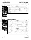
Aux Insert 1 Thru 6
This switching 1/4” TRS jack allows an external processor or EQ to be inserted into the
signal path of the Aux circuit. 1/3 Octave EQs or feedback suppressors are commonly
used here if the Aux send is used for on stage monitors. The tip carries the SEND signal
from the mixer, and the ring carries the RETURN signal back to the mixer. The insert-
send point is located directly after the Aux mix bus, the return comes back at the top of
the Aux level pot.
Tip is Send, Ring is Return, Sleeve is Audio Ground.
Send (output) impedance is 100 unbalanced
Return (input) impedance is 5K
unbalanced
Nominal Operating Level= -2 dBu
NOTE: To avoid any degradation of the mixer's output signal, any processing gear patched
into any insert point should have a low impedance output (<100
) and must be capable of
cleanly driving a 2K
load to +21 dBu.
Aux OUT TRS Jacks 1 Thru 6
The six Aux master outputs are available on these 1/4” TRS jacks. These jacks are
ground-compensated, impedance-balanced. Tip is driven output, Ring is GC sense return,
Sleeve is chassis.
Aux OUT XLRs 1 Thru 6
The six Aux master outputs are also available on these male XLR jacks. These jacks are
wired in parallel with the corresponding TRS jacks. Pin 2 is the driven output, Pin 3 is the
GC sense return, Pin 1 is chassis.
NOTE: Either type of output jack may be used, but you should avoid using both the TRS
and XLR simultaneously. Because the jacks are parallel-wired, the shared GC pin can cause
ground-hum to appear in one of the output jacks if the GC circuit is trying to correct for a
ground-difference in the other output jack.
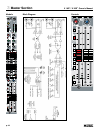
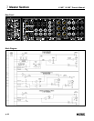
Group Inserts 1 Thru 4
This switching 1/4” TRS jack allows an external processor or EQ to be inserted into the sig-
nal path of the Group circuit. EQs or compressors are commonly used here if the Group is
used for sub-mixing. The tip carries the SEND signal from the mixer, and the ring carries the
RETURN signal back to the mixer. The insert-send point is located directly after the Group
mix bus, the return comes back at the top of the Group master fader
Tip is Send, Ring is Return, Sleeve is Audio Ground.
Send (output) impedance is 100
unbalanced
Return (input) impedance is 5K
unbalanced
Nominal Operating Level= -2 dBu
NOTE: To avoid any degradation of the mixers’s output signal, any processing gear patched
into any insert point should have a low impedance output (<100
) and must be capable of
cleanly driving a 2K
load to +21 dBu.
Group OUT TRS Jacks 1 Thru 4
The four Group master outputs are available on these 1/4” TRS jacks. These jacks are
ground-compensated, impedance-balanced. Tip is driven output, Ring is GC sense return,
Sleeve is chassis.
p. 49