


3.6.2 Connector J1
Pin
#
Short
Form
Function
Description
1 EN+ Enable + Positive voltage input of the “Amplifier Enable” function.
To enable operation of the amplifier, the optocoupler
must be energized by applying voltage between this pin
(+) and pin J1/22 (-).
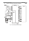
The optocoupler is isolated from the amplifier. See Figure
3-4.
“OFF” voltage: 0 V < Vin < 1 V.
“ON” voltage: 2.5 V < Vin < 10 V, 5 V typically with
current consumption 2.5 mA.
2 AOK Amplifier OK When the amplifier is under normal operating conditions,
this output is in the “active low“ state. When a failure
occurs, this output is changed to the “open” state.
The optocoupler is an isolated, open collector NPN type.
See Figure 3-4.
Maximum voltage = 30 V
Maximum current = 8 mA
“On” voltage: V
OUT(On)
< 0.8 V
Refer to Section 4.4.
3 SO1 Status output 1 Specifications same as in pin J1/2.
4 HA Hall A input Logic levels: TTL
Maximum input voltage
: 15 VDC.
5 HB Hall B input Logic levels: TTL
Maximum input voltage
: 15 VDC.
6 HC Hall C input Logic levels: TTL.
Maximum input voltage: 15 VDC.
7
LATCH Latch mode Latch mode input. For more details see the Latch Mode
section in Chapter 4.
8 ECLRET Current limits
return
Current limit signals return.
9 ECLC External
current limit
continuous
External voltage scales down the rated value.
Voltage range: 0 V to 3.75 V (3.75 V = rated Ic)
Refer to Section 4.3.
10 CM Current
monitor
Analog output with a scale of ± 3.9 V for ± Ip.
Output resistance: 1 kΩ
11 CREF+ Current
command
positive
Positive input of a differential amplifier:
Input operating voltage range: ±3.75 V
Maximum input voltage: ±20 V
Maximum common mode voltage: ±6 V
Differential input impedance: 40 kΩ
Refer to Section 4.2.
12
CREF- Current
command
negative
Negative input of a differential amplifier.
Same specification as in pin J1/11.
13 CMRET Current
monitor return
Current monitor (CM) signal return.
Ocarina/Castanet Installation Guide Installation
MAN-OCSIG (Ver. 1.2)
3-6