


wwwwww
..
ffeennddeerr..ccoomm
✧
wwwwww
..mmrrggeeaarrhheeaadd..nneett
6
FF
FF
ee
ee
nn
nn
dd
dd
ee
ee
rr
rr
®
11
11
11
11
55
55
PP
PP
rr
rr
oo
oo
EE
EE
xx
xx
tt
tt
LL
LL
oo
oo
uu
uu
dd
dd
ss
ss
pp
pp
ee
ee
aa
aa
kk
kk
ee
ee
rr
rr
EE
EE
nn
nn
cc
cc
ll
ll
oo
oo
ss
ss
uu
uu
rr
rr
ee
ee
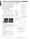
Your new 115 Pro Ext Bass Loudspeaker Enclosure is
constructed from 3/4" (1.9 cm) 13-ply Baltic Birch
Plywood and is capable of handling 250 Watts of con-
tinuous power. The 115 Pro Ext features a 15” (38.1
cm) speaker with 67 oz (1.90 kg) magnet and is
designed for use with the Fender
®
400 Pro Combo
amplifier or other professional quality bass amplifier.
Please read these instructions and the instructions that
came with your amplifier before making connections.
Follow all equipment caution and safety labeling.
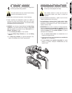
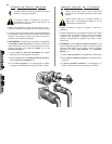
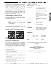
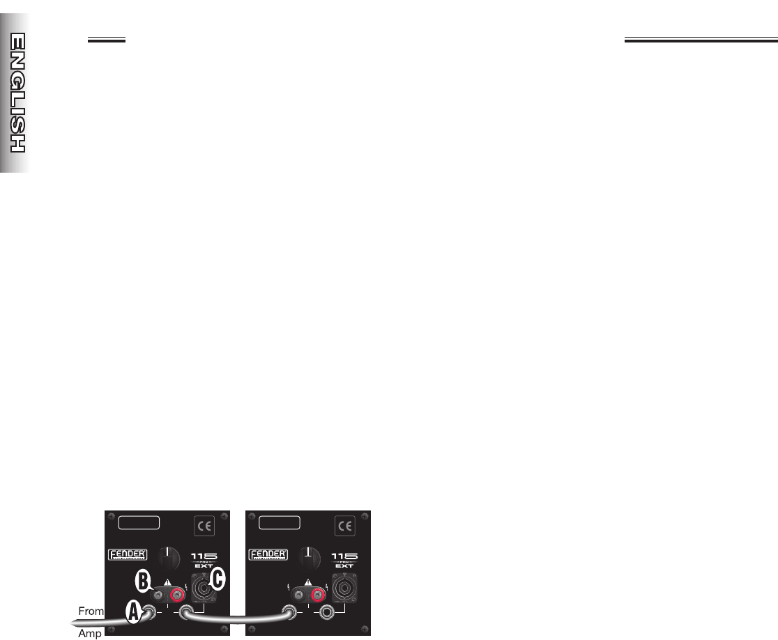
SPEAKER CONNECTIONS
Use 16 gauge (or heavier) speaker cable with one of the
three types of input connections on your 115 Pro Ext:
A) Phone jacks with a standard 1/4" plug
B) Binding posts with dual “banana” plug or
stripped wires
C) Speakon
®
connector with Speakon
®
plug
Multiple 115 Pro Ext cabinets can be linked as illustrat-
ed, when additional output is needed. Note: Follow the
speaker impedance load guidelines set by the manufac-
turer of your amplifier to avoid damage to your equip-
ment.
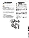
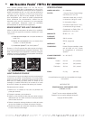
HORN TWEETER
The horn tweeter is protected from power-overload
damage by an incandescent lamp. If the horn tweeter
stops responding, replace the lamp as you would a
blown fuse. The lamp and a spare (reorder P/N
051857) are located on the circuit board on the inside
of the input jack panel.
Lamp Replacement:
1) Remove the 4 screws from the input jack panel cor-
ners.
2) Pull the panel out, then up.
3) Use a small flathead screwdriver to remove the
blown lamp which is visible through a cutout in the
circuit board.
4) Remove the spare lamp stowed on the side of the
circuit board and install it where the blown lamp was
located.
5) Install the input jack plate in the reverse order of
removal.
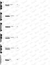
SPECIFICATIONS
PART NUMBER: 22-17800-000
DRIVERS: One 15” (38.1 cm) Fender
Special Design Cast Frame
Woofer
2.5" (6.4 cm) Voice Coil,
67 oz (1.90 kg) Magnet
One Horn Tweeter
1" (2.5 cm) Voice Coil, 8 oz
(0.23 kg) Magnet
CABINET: 3/4" (1.9 cm) 13-ply
Baltic
Birch
Plywood
SENSITIVITY: 96 dB, 1 Watt - 1 Meter
POWER HANDLING: 250 Watts, Continuous
500 Watts, Program
IMPEDANCE:4 Ω
CONNECTIONS: Dual, Parallel Wired, 1/4”
High Current Input Jacks,
Binding Posts and
Speakon
®
Connector
ENCLOSURE VOLUME: VB = 3.0 ft
3
(85 l)
DIMENSIONS:
Height: 21.3 in (54.0 cm)
Width: 23.0 in (58.4 cm)
Depth: 16.1 in (40.9 cm)
WEIGHT: 60 lb (27.3 kg)
Product specifications are subject to change without notice.
A PRODUCT OF:
FENDER MUSICAL INSTRUMENTS CORP.
CORONA, CA USA
Fender
®
is a registered trademark of FMIC,
Speakon
®
is a registered trademark of Neutrik.
Copyright © 2003 FMIC
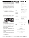
WARNING:
FENDER LOUDSPEAKER SYSTEMS
ARE CAPABLE OF PRODUCING
VERY HIGH SOUND PRESSURE
LEVELS WHICH MAY CAUSE
TEMPORARY OR PERMANENT
HEARING DAMAGE. USE CARE
WHEN SETTING AND ADJUSTING
VOLUME LEVELS DURING USE.
POWER RATING
250W CONTINUOUS
500W PROGRAM
SERIAL NUMBER
HORN
LEVEL
PARALLEL
INPUTS
MIN. MAX.
A PRODUCT OF:
FENDER MUSICAL
INSTRUMENTS CORP.,
CORONA, CA U.S.A.
MADE IN MEXICO
MODEL
IMPEDANCE
4
Ω