


wwwwww
..
ffeennddeerr..ccoomm
✧
wwwwww
..mmrrggeeaarrhheeaadd..nneett
7
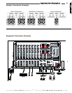
Channel Contr
Channel Contr
ols
ols
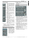
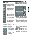
1. Pan – Controls relative level of input
channel in Left and Right program
mixes. To route the signal to both
channels equally, leave this in the
center. In Main/Monitor mode, only
the line level L/R outputs will be
affected.
2. Level – Controls the level of input
channel sent to the Left and Right
Program mixes; or if in
Main/Monitor mode, controls the
level sent to the Main program mix.
3. DFX – Adjusts the amount of signal
level from the channel sent to the
effects mix.
4. Monitor – Controls the level of input
channel sent to the monitor mix.
5. Low – Bass tone control +/- 15 dB
shelving at 80 Hz.
6. Mid – Midrange tone control +/- 12
dB boost/cut at 2.5kHz.
7. High – High tone control +/- 15 dB
shelving at 8kHz.
8. Pad – Input channel pre-amp gain.
Set to -20 dB for hot inputs that
cause distortion.
9. Line Input – 1/4 inch TRS, suited for
use with line level inputs such as
high impedance microphones,
keyboards, drum machines,
outboard effects etc. This input
accepts both balanced and
unbalanced cables.
10. Mic Input – The 3 pin XLR balanced female
connector is intended for low impedance
microphones. Pins 2 and 3 provide phantom power
for condenser microphones.
Warning: connect only one device to each channel—do
not use both line and mic inputs at the same time.
Digital Ef
Digital Ef
fects
fects
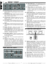
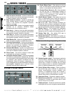
11. DSP Peak LED – The DSP
peak indicator lights when
the DSP circuit is clipping
(distorting). If distortion is
heard while this LED is lit,
reduce the channel effects
levels until the indicator
goes dark. Increase DFX
master to compensate.
12. Program – This knob selects a preset from the list
of effects to the right.
13. Effects On/Off – This switch turns on or off the
internal DSP.
Main Section
Main Section
14. Master Graphic Equalizers - These 7 band
equalizers consist of active band pass / reject filters
spaced evenly across the audio range. Moving the
sliders up and down boosts or cuts the gain up to
12 dB at the indicated frequency.
15. Amp Protection LEDs - These LEDs signify the
protection circuit is active for the indicated
amplifier; this may be due to a short circuit at the
speaker terminals, or a high heatsink temperature.
If lit, check speaker connections for a short circuit,
or reduce master volume.
16. Level Indicators - These indicators show the
overall level being output to the Left / Monitor or
Right/Main master mixes. If the top, red LED is
flashing, reduce the corresponding master volume
to prevent possible damage to your speakers.
17. Left Master Volume - Adjusts the overall volume
level for the left program mix.
18. Right Master Volume - Adjusts the overall volume
level for the right program mix.
19. Meter Mode - This switch determines which mix is
being monitored by the level indicators.
CC
CC
oo
oo
nn
nn
tt
tt
rr
rr
oo
oo
ll
ll
ss
ss