


ADJUSTABLE FEATURES
TRANSISTOR PUMP CONTROLS Page 65
August 1999
of 0.375 volts each whereas, a setting of 4 will be added in
15 steps of 0.375 volts each.
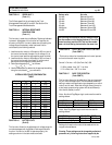
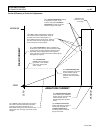
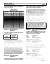
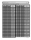
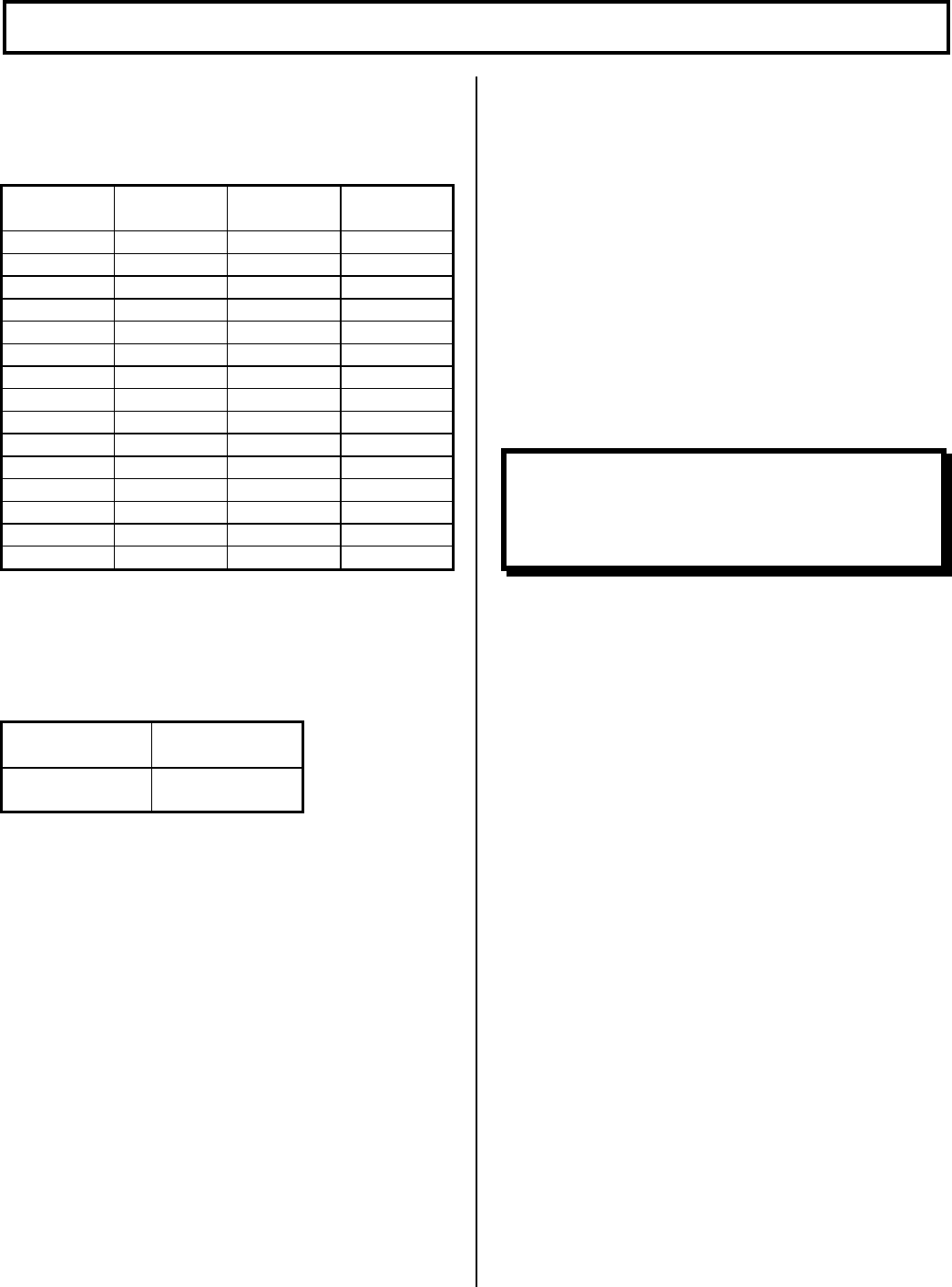
SPEED / TORQUE
COMPENSATION TABLE
SETTING
VOLTAGE
DROP
SETTING
VOLTAGE
DROP
2 11.44 17 1.34
3 7.60 18 1.27
4 5.72 19 1.20
5 4.57 20 1.14
6 3.81 21 1.09
7 3.27 22 1.04
8 2.86 23 0.99
9 2.54 24 0.95
10 2.28 25 0.91
11 2.08 26 0.88
12 1.90 27 0.85
13 1.76 28 0.82
14 1.63 29 0.79
15 1.52 30 0.76
16 1.43 31 0.74
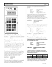
FUNCTION 17: CARD TYPE SELECTION
(Push CONT 2)
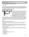
This function should be set in accordance with the control
type in use in the vehicle:
Function
Without Pump
Ctr/PMT
High C/L
BDI Lockout
63 to 71
BDI Lockout means that the BDI signal from the traction
control must be present in order for the pump control to
operate. This control will stop operation when the battery
state of charge reaches 10%.
Settings for these functions should be made in between the
values shown.
Warning: These setting must be changed by authorized
personnel only, following instructions supplied by the
manufacturer. Card type selection must be made within
the capabilities of the TRANSISTOR control panel used
and the supporting electro-mechanical devices. Failure to
comply with proper application standards could result in
mis-operation or damage to the control and/or motors.
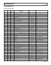
FUNCTION 28: FAULT COUNT POINTER
(Push CONT 13)
This register contains the location of the last stored status
code recorded of the 16 stored status codes. These stored
status codes have caused a PMT controller shutdown
and/or disruption of normal vehicle operation.
To determine which stored status code was the last one
recorded, read the number stored in Function 28. Using the
Memory Map (See Section 8.1) for your logic card, match
the “stored status code pointer number” (the number
shown in (bold italics) in the HS (Handset) number column)
on the memory map, with the number obtained from
Function 28. This will be the last stored status code
recorded.
Note: When scrolling the stored status code register, the
register always starts at status code 1 and scrolls to
status code 16. Instructions for scrolling the register are
in Section 6.3.2 of this instruction booklet.
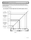
FUNCTION 48: MODE 1 - CONTROLLED ACCELERATION
(Push CONT 1)
This function allows for the adjustment of the rate of time it
takes for the control to accelerate to 96% applied battery
voltage to the motor on hard acceleration.
Range 0.1 to 22.0 seconds
Setting 0 to 255
Resolution 0.084 seconds per set unit
Example: Setting of 20 = 1.8 seconds C/A
FUNCTION 49: MODE 1 - SPEED LIMIT 2 (SL2)
(Push CONT 2)
This function allows for the adjustment of the speed limit
(maximum battery volts to the motor) when the SL2 limit
switch input signal is received by the control card. SL2
limit switch is a normally open switch connected to battery
negative, the switch closing enables speed limit.
Range 0% to 100% battery volts
Setting 0 to 255
Resolution 0.375 volts per set unit
Example: Setting of 50=18.75 volts
FUNCTION 50: MODE 1 - SPEED LIMIT 3 (SL3)
(Push CONT 3)
This function allows for the adjustment of the speed limit
(maximum battery volts to the motor) when the SL3 limit
Note: The following functions have function numbers
larger than the numbers on the Handset keyboard. To
access these functions, push the CONT key and the
number shown in the following instructions at the same
time. THE KEY SWITCH MUST BE CLOSED.