


Page 3
Introduction
Congratulations on purchasing the Gemini BPM-500 mixer. This state of
the art mixer is backed by a three year warranty, excluding crossfader and
channel slides. Prior to use, we suggest that you carefully read all the
instructions.
Features
• 4 Stereo Channels
• State of the Art Cue Section
• 3 Phono/Line Convertible, 5 Line, and 3 Mic Inputs
• BPM Displays and Beat Offset Indicators
• Cut Feature for Low, Mid and High for each channel
• Gain, High, Mid and Low tone controls for each channel
• Talkover
• Loop
• Balanced and Unbalanced Master Outputs
• Booth and Record outputs
• Dual mode display
Cautions
1. All operating instructions should be read before using this equipment.
2. To reduce the risk of electrical shock, do not open the unit. There are
NO USER REPLACEABLE PARTS INSIDE. Please refer servicing to a
qualified service technician.
In the U.S.A., if you have any problems with this unit,
call 1-732-969-9000 for customer service. Do not return
equipment to your dealer.
3. Do not expose this unit to direct sunlight or to a heat source such as a
radiator or stove.
4. This unit should be cleaned only with a damp cloth. Avoid solvents or
other cleaning detergents.
5. When moving this equipment, it should be placed in its original carton
and packaging. This will reduce the risk of damage during transit.
6. DO NOT EXPOSE THIS UNIT TO RAIN OR MOISTURE.
7. DO NOT USE ANY SPRAY CLEANER OR LUBRICANT ON ANY
CONTROLS OR SWITCHES.
Connections
1. Before plugging in the power cord, make sure that the VOLTAGE
SELECTOR (44) switch is set to the correct voltage.
NOTE: This product is double insulated and not intended to
be grounded.
2. Make sure that the POWER (39) switch is in the off position. The
POWER LED (38) will be off.
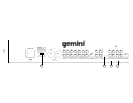
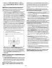
3. The BPM-500 is supplied with 4 sets of amp output jacks. The
BALANCED OUTPUT (45) jacks are used to connect to your main
amplifier using standard XLR cables. We recommend using the
balanced amp outputs if the cables to your amp are 25 feet or more.
BALANCED OUTPUTS have three separate conductors, two of which
are signal (positive and negative) and one shield (ground). Pin 1 is
ground (shield). Pin 2 is signal hot (positive). Pin 3 is signal cold
(negative). The MAIN OUTPUT (46) jacks are unbalanced and used to
connect to your main amplifier. The REC OUTPUT (48) jacks can be
used to connect the mixer to the record input of your recorder enabling
you to record your mix. The BOOTH OUTPUT (47) jacks allow you to
hook up an additional amplifier.
4. The MIC 1 (1) input (found on the front panel) accepts a 1/4" or XLR
connector.
The MIC 2 (63) input and the MIC 3 (53) input (found on the
rear panel) accept 1/4" connectors. All accept balanced and
unbalanced microphones.
5. On the rear panel are 3 stereo PHONO/LINE (55, 59, 62) inputs and 5
stereo LINE (51, 52, 54, 57, 60) inputs. The PHONO/LINE SWITCH
(56) enables you to set the (55) input to Phono or Line. The PHONO/
LINE SWITCH (58) enables you to set the (59) input to Phono or Line.
The PHONO/LINE SWITCH (61) enables you to set the (62) input to
Phono or Line. The phono inputs will accept only turntables with a
magnetic cartridge. A GROUND SCREW (64) for you to ground your
turntables is located on the rear panel. The stereo line inputs will
accept any line level input such as a CD player, a cassette player, etc.
6. Headphones can be plugged into the front panel mounted
HEADPHONE (43) jack.
7. The BPM-500 comes with a front panel BNC LIGHT (37) jack. This
jack is for use with a gooseneck light like the Gemini GNL-700.
8. There are LOOP INPUTS (50) and LOOP OUTPUTS (49) located on
the rear panel. If you are using an outboard signal processor, you can
use the LOOP OUTPUTS (49) to send the signal to the device and the
LOOP INPUTS (50) to bring the signal back in to the mixer. The unit
comes with jumpers to be used with the loop inputs and outputs. Keep
the jumpers in the unit if you are not using the loop to prevent
interruptions in your music program.
Using the Ground Lift Switch
Depending on your system configuration, sometimes applying the ground
will create a quieter signal path. Sometimes lifting the ground can
eliminate ground loops and hum to create a quieter signal path.
1. With the mixer on, listen to the system in idle mode (no signal present)
with the ground applied (the GROUND LIFT SWITCH (65) in the left
position).
2. Then turn the power off before moving the GROUND LIFT SWITCH
(65). Lift the ground by moving the GROUND LIFT SWITCH to the
right, turn the power back on and listen to determine which position will
provide a signal devoid of background noise and hum. Keep the
GROUND LIFT SWITCH in the ground position if the noise level
remains the same in either position.
CAUTION: DO NOT TERMINATE THE AC GROUND ON THE POWER
MIXER IN ANY WAY. TERMINATION OF THE AC GROUND CAN BE
HAZARDOUS.
Operation
1. POWER ON: Once you have made all the equipment connections to
your mixer, press the POWER SWITCH (39). The power will turn on and
the POWER LED (38) will glow RED.
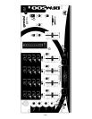
2. CHANNEL 1: The GAIN (8), HIGH (9), MID (10), and LOW (11)
controls allow you to fully adjust the selected source. Switch # (12)
allows you to select the PHONO 1/LINE 1 (62) or the LINE 2 (60)
input. The CHANNEL SLIDE (13) controls the input level of this
channel.
3. CHANNEL 2: The GAIN (8), HIGH (9), MID (10), and LOW (11)
controls allow you to fully adjust the selected source. Switch # (14)
allows you to select the PHONO 2/LINE 3 (59) or the LINE 4 (57) input.
The CHANNEL SLIDE (15) controls the input level of this channel.
4. CHANNEL 3: The GAIN (8), HIGH (9), MID (10), and LOW (11)
controls allow you to fully adjust the selected source. Switch # (16)
allows you to select the PHONO 3/LINE 5 (55) or the LINE 6 (54) input.
The CHANNEL SLIDE (17) controls the input level of this channel.