Page 4
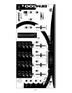
5. CHANNEL 4: The GAIN (8), HIGH (9), MID (10), and LOW (11)
controls allow you to fully adjust the selected source. Switch # (18)
allows you to select the LINE 7 (52), LINE 8 (51) or the MIC 3 (53)
input. The CHANNEL SLIDE (19) controls the input level of this
channel.
NOTE: There is Low, Mid and High equalization for each
channel with an extremely wide range of adjustment.
SUGGESTION: You can use the Cut Features on each channel to
remove Low, Mid and/or High to create special effects.
6. CROSSFADER SECTION: The CROSSFADER (26) allows the mixing
of one source into another. The BPM-500 features an assignable
crossfader. The ASSIGN (23, 28) switches allow you to select which
channel will play through each side of the crossfader. The ASSIGN (23)
switch has 4 settings (1, 2, 3 or 4) and allows you to select channel 1, 2,
3 or 4 to play through the left side of the crossfader. The ASSIGN (28)
switch has 4 settings (1, 2, 3 or 4) and allows you to select channel 1, 2,
3 or 4 to play through the right side of the crossfader. There are two OFF
(22, 30) buttons for the crossfader. When the OFF (22) button is
pressed, the left side of the crossfader will be inactive and the OFF
LED (21) will light. When the OFF (30) button is pressed, the right side
of the crossfader will be inactive and the OFF LED (29) will light. Using
the OFF button, be sure to deactivate the crossfader before changing
the ASSIGN setting. This will avoid any click or popping sound in your
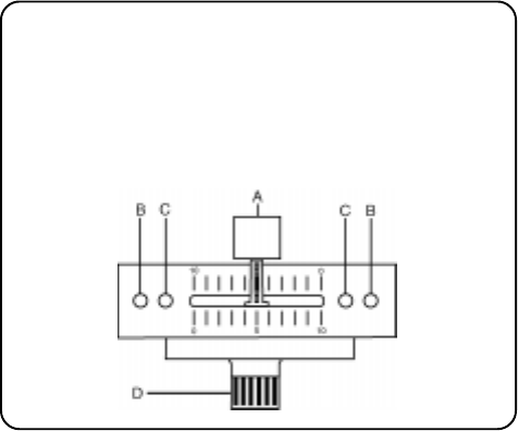
signal while you are changing the assign setting. The CROSSFADER
(26) in your unit is removable and if the need arises can be easily
replaced. Crossfader units are available in three varieties. Part # RF-45
(which is identical to the crossfader supplied with the mixer) has a 45
mm travel from side to side. Part # RF-30 is available with a 30 mm
travel distance. Also available is the PSF-45 with a special curve
designed for scratch mixing. Just purchase one of these crossfader
units from your Gemini dealer and follow these instructions:
1. Unscrew the outside FADER PLATE SCREWS (B). Do not
touch the INSIDE SCREWS (C).
2. Carefully lift the fader and unplug the CABLE (D).
3. Plug the new fader into the cable and place it back in the
mixer.
4. Screw the fader to the mixer.
7. BPM DISPLAY: There are BPM DISPLAYS (24, 27) for the two
channels assigned to each side of the CROSSFADER (26). They
update approximately every 2.5 seconds and digitally display the Beats
Per Minute allowing you to match the beats visually. BPM DISPLAY
(24) reflects the Beats Per Minute of the channel assigned to the left
side of the CROSSFADER, and BPM DISPLAY (27) reflects the Beats
Per Minute of the channel assigned to the right side of the
CROSSFADER.
NOTE: A [- -] reading will appear on the BPM DISPLAY if the
track has unclear beats. The [- -] reading will also appear if
there is no signal present.
8. The BEAT OFFSET INDICATORS (25) light when the tracks of the two
channels assigned to the crossfader are within 11 BPMs of each other
and display how aligned the beats of the two channels are. When the
RED LEDs light, the beats are not aligned. When the YELLOW LEDs
light, the beats are almost aligned. When the GREEN LED lights, the
beats are aligned perfectly.
NOTE: If the diffence between the two channels beats
exceed 11 BPM, the BEAT OFFSET INDICATORS will not
light.
SUGGESTION: You can use the BPM DISPLAYS to determine which
tracks have similar or the same Beats Per Minute. When mixing two tracks
with similar Beats Per Minute, you can use one source’s pitch control to
align the Beats Per Minute with the other source’s BPM. The BPM
DISPLAYS and the BEAT OFFSET INDICATORS update every 2.5
seconds and will reflect the change in BPM and indicate when the beats
are aligned.
NOTE: Beat mixing is a skill that requires practice. Not
every track has a strong beat, and beat mixing works best
with tracks with clear and strong beats.
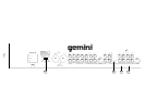
9. LOOP SECTION: Removing the jumpers from the LOOP OUTPUT (49)
and LOOP INPUT (50) jacks will activate the loop. Any device
connected to the LOOP OUTPUT (49) and LOOP INPUT (50) jacks will
be inserted into the signal path.
10.OUTPUT CONTROL SECTION: The level of the AMP OUT (45, 46) is
controlled by the MASTER (35) slide. Activating the MONO (33) button
(the mono LED will light) makes the overall output mono. The BOOTH
(36) control adjusts the level of the BOOTH OUTPUT (47). HINT: The
booth output is used by some DJs to run monitor speakers in their DJ
booth. You can also use it as a second ZONE or AMP output.
NOTE: The RECORD OUT (48) has no level control. The level
is set by the channel slides and the gain controls of the
selected channel. The tonal qualities are set by the low, mid
and high controls of that same channel.
11. TALKOVER SECTION: The purpose of the talkover section is to allow
the program playing to be muted so that the mic can be heard above
the music. The MIC/TALKOVER SWITCH (7) controls MIC 1 and MIC
2 and has three settings. When the MIC/TALKOVER SWITCH (7) is in
the bottom position, MIC 1 and MIC 2 and talkover are off. When the
MIC/TALKOVER SWITCH (7) is in the center position MIC 1 and MIC 2
are on, the MIC INDICATOR (6) will glow, but talkover is off. When the
MIC/TALKOVER SWITCH (7) is in the top position, MIC 1 and MIC 2
and talkover will be on and the volume of all sources except the Mic
inputs are lowered by 16 dB. The TREBLE (2) and BASS (3) controls
allow you to fully adjust the tone of MIC 1 and MIC 2. MIC 1 LEVEL (5)
controls the level of MIC 1. The MIC 2 LEVEL (4) controls the level of
MIC 2.
12. CUE SECTION: By connecting a set of headphones to the
HEADPHONE (43) jack, you can monitor any or all of the channels.
Press the CUE ASSIGN (20) buttons for channels 1 - 4 to select the
channel or channels to be monitored and their respective LED
indicators will glow. Use the CUE LEVEL (40) control to adjust the cue
volume without effecting the overall mix. By moving the CUE PGM PAN
(42) control to the left you will be able to monitor the assigned cue
signal. Moving the control to the right will monitor the PGM (program)
output. Use the CUE SPLIT (41) button to split the signals from cue
and program so that cue will be heard in one earphone and program
will be heard in the other earphone.
13. DISPLAY: The peak hold, dual function DISPLAY (31) indicates either
the MASTER (45, 46) output left and right levels OR the the selected
cue and program (premaster output) levels. You can choose the option
you want by pressing the DISPLAY (32) button.
NOTE: When the DISPLAY (31) is in the cue/program mode,
by adjusting GAIN (8), you can increase or decrease the
signal to match the other channels signal.