


Page 3
Introduction
Congratulations on purchasing the Gemini PMX-60 mixer. This state of the
art mixer includes the latest features and is backed by a three year limited
warranty, excluding crossfader and channel slides. Prior to use, we
suggest that you carefully read all the instructions.
Features
• 2 Stereo channels
• 2 Phono/Line Convertible, 1 Phono, 1 Line and 1 Mic input
• 1/4" DJ Mic jack
• Gain controls for each channel
• Master output control
• Cue section
Cautions
1. All operating instructions should be read before using this equipment.
2. To reduce the risk of electrical shock, do not open the unit. There are
NO USER REPLACEABLE PARTS INSIDE. Please refer servicing to a
qualified service technician.
In the U.S.A., if you have any problems with this unit,
call 1-732-738-9003 for customer service. Do not return
equipment to your dealer.
3. Do not expose this unit to direct sunlight or to a heat source such as a
radiator or stove.
4. This unit should be cleaned only with a damp cloth. Avoid solvents or
other cleaning detergents.
5. When moving this equipment, it should be placed in its original carton
and packaging. This will reduce the risk of damage during transit.
6. DO NOT EXPOSE THIS UNIT TO RAIN OR MOISTURE.
7. DO NOT USE ANY SPRAY CLEANER OR LUBRICANT ON ANY
CONTROLS OR SWITCHES.
Connections
1. Make sure that the POWER (6) switch is in the OFF position. This unit
comes supplied with a 15 volt AC adaptor. Plug the male pin of the
adaptor into the rear panel POWER JACK (7). Then plug the adaptor
into a proper power source.
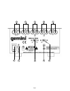
2. The MASTER OUTPUT (1) jacks are unbalanced and used to connect
to your main amplifier.
3. The DJ MIC (15) input (found on the front panel) accepts a 1/4"
connector and balanced and unbalanced microphones.
4. On the rear panel are 2 stereo PHONO/LINE (3, 4) inputs, 1 stereo
PHONO (5) input and 1 stereo LINE (2) input. The PHONO/LINE
SWITCHES (8, 10) enable you to set the (3, 4) inputs to Phono or Line.
The phono inputs will accept only turntables with a magnetic cartridge.
A GROUND SCREW (9) for you to ground your turntables is located on
the rear panel. The stereo line inputs will accept any line level input
such as a CD player, a cassette player, etc.
5. Headphones can be plugged into the front panel mounted
HEADPHONE (28) jack.
Operation
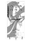
1. POWER ON: Once you have made all the equipment connections to
your mixer, press the POWER (6) switch. The power will turn on and
the POWER LED (19) will glow RED.
2. CHANNEL 1: The GAIN (12) control allows you to individually adjust
the gain of the channel. Switch # (13) allows you to select the
PHONO 1 (5) or the PHONO 2/LINE 1 (4) input. The CHANNEL SLIDE
(14) controls the input level of this channel.
3. CHANNEL 2: The GAIN (25) control allows you to individually adjust
the gain of the channel. Switch # (26) allows you to select the
PHONO 3/LINE 2 (3) or the LINE 3 (2) input. The CHANNEL SLIDE (27)
controls the input level of this channel.
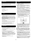
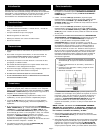
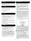
4. CROSSFADER SECTION: The CROSSFADER (22) allows the mixing of
one source into another. The left side of the CROSSFADER (22) is
CHANNEL 1 and the right side is CHANNEL 2. The CROSSFADER (22)
in your unit is removable and if the need arises can be easily replaced.
Crossfader units are available in three varieties. Part # RF-45 (which
is identical to the crossfader supplied with the mixer) has a 45 mm
travel from side to side. Part # RF-30 is available with a 30 mm travel
distance. Also available is the PSF-45 with a special curve designed
for scratch mixing. Just purchase one of these crossfader units from
your Gemini dealer and follow these instructions:
1. Unscrew the outside FADER PLATE SCREWS (B). Do not
touch the INSIDE SCREWS (C).
2. Carefully lift the fader and unplug the CABLE (D).
3. Plug the new fader into the cable and place it back in the
mixer.
4. Screw the fader to the mixer.
The CROSSFADER CURVE SWITCH (23) allows you to adjust the kind
of curve the crossfader has. When the switch is in the left position,
the curve is gradual and gentle. When the switch is in the right
position, the curve is steep and cutting (perfect for scratching). The
CROSSFADER REVERSE SWITCH (21) allows you to reverse the
crossfader so that CHANNEL 2 is controlled by the left side of the
crossfader and CHANNEL 1 is controlled by the right side of the
crossfader.
NOTE: When the CROSSFADER REVERSE SWITCH
(21) is activated (moved to the right), only the crossfader
reverses. The Channel Slides and Gain do not reverse.
5. OUTPUT CONTROL SECTION: The level of the MASTER OUTPUT (1) is
controlled by the MASTER (24) control.
6. TALKOVER SECTION: The purpose of the talkover section is to allow
the program playing to be muted so that the mic can be heard above
the music. The MIC/TALKOVER (16) switch has three settings. When
the MIC/TALKOVER (16) switch is in the left position, the mic and
talkover are both off. When the MIC/TALKOVER (16) switch is in the
center position the mic is on, but talkover is off. When the MIC/
TALKOVER (16) switch is in the right position, the mic and talkover will
be on and the volume of all sources except the Mic input are lowered
by 16 dB. MIC LEVEL (11) controls the level of the MIC.
7. CUE SECTION: By connecting a set of headphones to the HEADPHONE
(22) jack, you can monitor either channel or both together. Move the
CUE SWITCH (25) to the left to monitor CHANNEL 1. Move the CUE
SWITCH (25) to the right to monitor CHANNEL 2. Move the CUE