


INTRODUCTION:
Congratulations on your purchase of a Gemini PMX-02 10" 2 Channel
Stereo Mixer. This state-of-the-art mixer features the latest technological
advances and is backed by a three year warranty, excluding the crossfad-
er and channel slides.
FEATURES:
- 10" 2 stereo channel mixer
- 4 line, 2 convertible phono/line, RCA inputs
- 3 band rotary line EQ with cut feature
- Easy removable face plate for user replaceable rail glide cross fader
- Ergonomically designed to be flush with turntable
- Smooth curved face plate
- Rotary gain channel control
- Display with bright LED
-Face plate located rotary Mic volume control
- Face plate located rotary cue volume control & Cue section fader allow-
ing cue mix
- Front located 1/4" Mic input & headphone output
- Dual ground screws for easy connectivity
- Master and record RCA outputs
CAUTIONS:
1. All instructions should be read before using this equipment.
2. To reduce the risk of electrical shock, do not open the unit. Please refer
all servicing needs to a Gemini-qualified service technician.
3. Do not expose this unit to direct sunlight or a heat source such as a radi-
ator or stove.
4. This unit should be cleaned only with a damp cloth. Avoid solvents or
other cleaning detergents.
5. When moving this equipment it should be placed in its original carton
and packaging. This will reduce the risk of damage during transit.
6. DO NOT EXPOSE THIS UNIT TO RAIN OR MOISTURE.
7. DO NOT USE SPRAY CLEANERS OR LUBRICANTS ON CON-
TROLS, SURFACES OR SWITCHES.
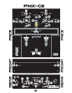
CONNECTIONS:
1. Ensure that the POWER (1) switch is in the OFF position prior to mak-
ing any connections. This unit comes with a 15 V AC adaptor. Plug the
adaptor into the rear panel POWER JACK (2) before plugging it into a
proper power source.
2. The PMX-02 has two outputs located on the back panel, the MASTER
and RECORD RCA OUTPUTS. Plug the MASTER RCA OUTPUT (3) into
your main amplifier to the main amplifier using standard audio cables with
RCA-type connectors. Plug the RECORD RCA OUTPUT (32) to the
record input of your recording unit.
3. Headphones may be plugged into the front panel-mounted HEAD-
PHONES (9) ¼" jack.
4. Microphones may be plugged into the front panel-mounted MICRO-
PHONE (8) ¼" jack.
5. The PMX-02 has 2 CONVERTIBLE PHONO/LINE RCA INPUTS locat-
ed on the back panel on either side of the MASTER RCA INPUTS. Facing
the back panel, the convertible RCA Input on your right is for PHONO 1/
LINE 1 (31). The convertible RCAinput on your left is for PHONO 2/ LINE
3 (6). Using the PHONO/ LINE SWITCH(ES) (4,28), located just below
each input, you may convert the PHONO to LINE and vice versa. Plug the
RCA's from your playable medium into each input to be connected to their
respective CHANNELS (20, 27). The PHONO INPUTS (6, 31) only accept
turntables with a magnetic cartridge. The STEREO LINE INPUTS
(6,7,30,31) only accept line level inputs such as a CD, DAT, MiniDisc, etc
and require the proper switch setting.
6. When using (a) turntable(s), you will need to ground the RCA cable(s)
by screwing in the grounding fork(s) to the GROUNDING SCREWS
(5,29)located in the back panel of the PMX-02 mixer. Attach each PHONO
ground line to the DUAL GROUND THUMB SCREWS (5,29). This is
located adjacent to each PHONO INPUT (6, 31).
NOTE: Not attaching a ground may cause a system "hum."
OPERATION:
1. POWER ON: Once all equipment connections have been made, press
POWER (1) switch. Power is ON when the VU METER (10) power LEDs
are illuminated.
2. CHANNEL 1: The GAIN (19), HIGH (16), MID (17), and LOW (18) con-
trols allow you to fully adjust the selected source. The PH-1/LN-1 (31)
switch located on the rear panel allows you to select PHONO 1 or
LINE 1. The PHONO1/LINE1-LINE 2 (11) switch located on the front
allows you to switch from PHONO 1 to LINE 2 or LINE 1 to LINE 2. CHAN-
NEL 1 SLIDE (20) controls the input level of this channel.
3. CHANNEL 2: The GAIN (23), HIGH (24), MID (25), and LOW (26) con-
trols allow you to fully adjust the selected source. The PH-2/LN-3 (6)
switch a located on the rear panel allows you to select PHONO 2 or LINE
3. The PHONO2/LINE3-LINE 4 (22) switch located on the front allows you
to switch from PHONO 2 to LINE 3 or LINE 3 to LINE 4. CHANNEL 2
SLIDE (27) controls the input level of this channel.
4. CROSSFADER SECTION: The CROSSFADER (21) allows the mixing
of one source into another. The left side of the CROSSFADER (21) is
CHANNEL 1 and the right side is CHANNEL 2. The CROSSFADER (21)
in your unit is removable and if the need arises can be easily replaced.
Your Gemini mixer comes with an RG-45 PRO (RAILGLIDE™) Dual-Rail
Crossfader. Rail Glide™ crossfaders have internal dual stainless steel
rails that allow the slider to ride smoothly and accurately from end to end.
Also available is our CF-45 PRO (PROGLIDE™) Dual-Rail Crossfader.
This unique crossfader features, state of the art conductive plastic tech-
nology, for unlimited useage. Another crossfader we have available is the
PSF-45 (PRO SCRATCH™) crossfader with a special curve designed for
scratch mixing. Just purchase one from your Gemini dealer and follow the
instructions.
NOTE: Do not apply pressure while using the Crossfader. Lightly glide the crossfader
back and forth. Pressing down on the controls can bend contacts and cause a loss of
sound.
5. CUE: Cue facilitates the seamless blending of one recorded track into
another. Connecting a set of headphones to the HEADPHONES jack
allows you to monitor either Channel 1 or Channel 2. Select Channel 1 by
moving CUE FADER (13), located on the face panel, to CUE 1 on the left.
Listen to Channel 2 by moving CUE FADER to CUE 2 on the right. To mix
both Channels bring CUE to the middle so that both tracks may be heard.
Use CUE VOLUME (14) to adjust the headphone volume without affecting
the speaker-driven mix.
6. MIC SECTION: Connecting a microphone to the 1/4” MIC JACK (8)
allows voice amplification through the mixer to the stereo through the
MASTER OUTPUTS (3). This is controlled by the MIC VOLUME rotary
control (12).
7. DISPLAYS: The LED METER (10) indicates the MASTER OUTPUT (3)
left and right channel levels combined. LED METER (10) reflects the GAIN
(19,23), HIGH (16,24), MID (17, 25) and LOW (18, 26) rotary control
adjustments. The CHANNNEL SLIDES (20, 27) also affects the LED
METERS (10).
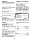
SPECIFICATIONS:
INPUTS:
Mic............................................................................1.5 mV 1 kOhm Balanced
Phono........................................................................................3 mV 47 kOhm
Line.......................................................................................150 mV 10 kOhm
OUTPUTS:
Amp.....................................................................................0 dB 1 V 400 Ohm
Max......................................................................................20 V Peak to Peak
GENERAL:
Bass (Channels 1-2)..................................................................+12 dB/-32 dB
Mid (Channels 1-2)......................................................................+8 dB/-32 dB
High (Channels 1-2)...................................................................+12 dB/-32 dB
Gain (Channels 1 - 2).......................................................................0 to -20 dB
Frequency Response..................................................20 Hz - 20 kHz +/- 2 dB
Distortion................................................................................Less than 0.02%
S/N Ratio.............................................................................Better Than 80 dB
Headphone Impedance........................................................................32 Ohm
Power Source Adapter.....................................................115 V/15 V AC 7.5 W
....................................................................................Or 230 V/15 V AC 7.5 W
Unit Dimensions.....................W 10" x H 3.3" x D 10.25" (254 x 84 x 260 mm)
Weight....................................................................................5.86lbs (2.66 kg)
NOTE: SPECIFICATIONS AND DESIGN ARE SUBJECT TO CHANGE WITHOUT NOTICE
FOR PURPOSE OF IMPROVEMENT.
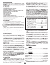
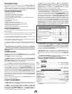
1. Unscrew the outside mixer
FACE PLATE screws and
remove the face plate. Then
remove FADER plate screws (B
& C).
2. Carefully lift the fader and
unplug the CABLE (D).
3. Plug the new fader into the
cable and place it back in the
mixer.
4. Screw to the fader plate to
the mixer and replace the mixer
FACE PLATE.
In the USA ~ if you experience problems with this unit call Gemini Customer Service
at: 1 (732) 738-9003. Do not attempt to return this equipment to your dealer.
(44)
USER REPLACEABLE RAIL GLIDE CROSS FADER