


Page 5
Sampler Operation
The PS-676i Sampler uses Dynamic RAM Memory and a 12 bit
microprocessor controller. The full bandwidth results in true sound
reproduction.
SAMPLE RECORD:
1. Put the MODE SELECTOR (36) switch into the WRITE position.
2. Select the source you want to sample from by pressing the
appropriate ASSIGN BUTTON(44).
3. The PS-676i is equipped with a SAMPLER REC/PLAY LEVEL(43)
control.When the MODE SELECTOR(36) is in the WRITE mode, this
control acts as a record level control. If the OVERLOAD
INDICATOR(42) is blinking, it means that the input signal you are going
to sample is too strong and will cause the sample to be distorted.
Lower the sample signal intensity by tuming the SAMPLER REC/PLAY
LEVEL(43) control counterclockwise.
4. If the OVERLOAD INDICATOR(30) is off, turn the SAMPLER REC/
PLAY LEVEL(43) control clockwise until the OVERLOAD
INDICATOR(42) begins to blink and then turn the SAMPLER REC/PLAY
LEVEL(43) counter clockwise until the OVERLOAD INDICATOR(42)
just goes off.
5. Tapping the START/STOP(39) button begins the sampling process
(the SAMPLER INDICATOR(38) will illuminate RED). Tapping the
START/STOP(39) button a second time ends the sample (the
SAMPLER INDICATOR(38) will tum off). If you do not tap the START/
STOP(39) button a second time, the sampling process will stop
automatically after 12 seconds.
SAMPLE PLAYBACK:
1. Put the MODE SELECTOR(36) switch into the SINGLE or REPEAT
position.
2. When the MODE SELECTOR(36) is in the SINGLE or REPEAT mode,
the SAMPLER REC/PLAY LEVEL(43) control acts as a Sampler Level
Control.
3. Tapping the START/STOP(39) button with the MODE SELECTOR(36)
in the SINGLE position will cause the sampler to playback one time
(the SAMPLER INDICATOR(38) will illuminate GREEN). Every push of
the START/STOP(39) button will restart the sample from the
beginning. Rapid pressing of the START/STOP(39) button will cause
a stuttering effect. Once the sample has started playback and the
START/STOP(39) button is not pushed a second time, the sample will
play to the end and then stop (the SAMPLER INDICATOR(38) will
illuminate turn off).
4. Tapping the START/STOP(39) button with the MODE SELECTOR(36)
in the REPEAT position will cause the sample to continuously play
over and over (the SAMPLER INDICATOR(38) will illuminate GREEN).
The START/STOP(39) button will act as an on/off switch. The first
push will start the sample, the second push will stop it.
ROBO PLAY:
1. With the ROBO PLAY(33) button in the OFF position (the ROBO PLAY
INDICATOR(34) will be OFF ) and the MODE SELECTOR(36) switch in
either the SINGLE or REPEAT mode, pressing the START/STOP(39)
will cause the sample to play along with the signal going through the
mixer.
2. When the ROBO PLAY(33) button is in the ON position (the ROBO
PLAY INDICATOR(34) illuminates RED), starting the sampler mutes the
signal going through the mixer. When the sample ends, the signal
automatically turns back on.
PITCH CONTROL:
The PS-676i comes equipped with a sampler PITCH(35) control. To get a
perfect sample, set the control to its center position and record the
sample.
✦
Your Gemini mixer comes with an
RG-45 PRO (RAIL
GLIDE) DUAL-RAIL CROSSFADER
. Rail Glide™
Crossfaders have internal dual stainless steel rails that allow the
slider to ride smoothly and accurately from end to end.
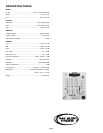
4. CROSSFADER SECTION: The CROSSFADER (25) allows the mixing
of one source into another. The left side of the CROSSFADER (25) is
channel 2 and the right side is channel 3.
5. BEAT INDICATORS:Each side of the CROSSFADER (25) has its own
BEAT INDICATOR (23,24). They flash at the low frequency peak
level allowing you to match the beats visually. BEAT INDICATOR (23)
will reflect the beat of the CH2 and BEAT INDICATOR (24) will do
the same for CH3.
6. OUTPUT CONTROL SECTION:The level of the AMP OUT (38) is
controlled by the MASTER (18) control. The BALANCE (17) control
will allow the Amp Out signal to be balanced between the left and
right speakers. The BOOTH (16) control adjusts the level of the
BOOTH OUTPUT (39).
HINT:BOOTH OUTPUT (39) is used by some DJs to run monitor
speakers in the DJ Booth. You can also use it as a second
ZONE or AMP output.
NOTE:The RECORD OUT (40) has no level control. The level is
set by the channel slides and the gain controls of the selected
channel. Tonal qualities are set by the low, mid and high
controls of that same channel.
7. TALKOVER SECTION:The purpose of the talkover section is to allow
the program playing to be muted so that the mic can be heard above
the music. When the TALKOVER (19) button is pushed, the
TALKOVER INDICATOR (28) will glow and the volume of all sources
except the Mic or whatever is connected to the PHONO/LINE (36)
input are reduced by -16 dB.
8. CUE SECTION:By connecting a set of headphones to the
HEADPHONE (4) jack, you can monitor any or all of the channels.
Select the correct CUE (21) button or buttons and their respective
CUE LED (5) indicators will glow. Use the CUE LEVEL (20) control to
adjust the headphone volume without effecting the overal mix. By
sliding the CUE PGM PAN (22) control to the left you will be able to
monitor the assigned cue signal. Sliding to the right will monitor the
PGM (program) output.
9. DISPLAY:The peak hold, dual function DISPLAY (26) indicates either
the MASTER (38) output left and right levels or the channel 2 and
channel 3 levels. You can choose the option you want by pressing
the DISPLAY (27) button.
NOTE:When the DISPLAY (27) is in the channel 2/channel
3 display mode, by adjusting the individual channel gain
and tone controls, you can increase or decrease the
signal to match the other channel’s signal. The channel
slides and crossfader have no effect on the display
readings.
10. The CROSSFADER CURVE SWITCH (31) allows you to adjust the
kind of curve the crossfader has Move switch to the “sharp” position to
make the curve steep and cutting (perfect for scratching ). Move
switch to the “gradual” position to make the curve gradual and gentle.
The CROSSFADER REVERSE SWITCH (32) allows you to reverse the
crossfader so that CHANNEL 3 is controlled by the left side of the
crossfader and CHANNEL 2 is controlled by the right side of the
crossfader.
NOTE: When the CROSSFADER REVERSE SWITCH (32) is
activated, only the crossfader reverses. The Channel
Slides, Gain, and tonal controls do not reverse.
F
F