


Page 4
4. CHANNEL 3: The GAIN (9), HIGH (10), MID (11), and LOW (12)
controls allow you to fully adjust the selected source. Switch # (17)
allows you to select the PHONO 3/LINE 5 (57) or the LINE 6 (56)
input. The CHANNEL SLIDE (18) controls the input level of this
channel.
5. CHANNEL 4: The GAIN (9), HIGH (10), MID (11), and LOW (12)
controls allow you to fully adjust the selected source. Switch # (19)
allows you to select the LINE 7 (55), LINE 8 (54) or the MIC 3 (65)
input. The CHANNEL SLIDE (20) controls the input level of this
channel.
NOTE: There is Low, Mid and High equalization for each
channel with an extremely wide range of adjustment.
SUGGESTION: You can use the Cut Features on each channel to
remove Low, Mid and/or High to create special effects.
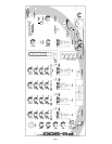
6. CROSSFADER SECTION: The CROSSFADER (22) allows the
mixing of one source into another. The PS-900 PRO features an
assignable crossfader. The ASSIGN (21, 23) switches allow you to
select which channel will play through each side of the crossfader.
The ASSIGN (21) switch has 5 settings (OFF, 1, 2, 3 or 4) and allows
you to select channel 1, 2, 3 or 4 to play through the left side of the
crossfader. The ASSIGN (23) switch has 5 settings (OFF, 1, 2, 3 or
4) and allows you to select channel 1, 2, 3 or 4 to play through the
right side of the crossfader. With the ASSIGN switch in the off
position, that side of the crossfader will be inactive. The
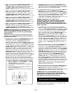
CROSSFADER (22) in your unit is removable and if the need arises
can be easily replaced. Crossfader units are available in three
varieties. Part # RF-45 (which is identical to the crossfader supplied
with the mixer) has a 45 mm travel from side to side. Part # RF-30 is
available with a 30 mm travel distance. Also available is the PSF-45
with a special curve designed for scratch mixing. Just purchase one
of these crossfader units from your Gemini dealer and follow these
instructions:
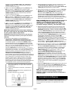
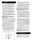
1. Unscrew the outside FADER PLATE SCREWS (B). Do
not touch the INSIDE SCREWS (C).
2. Carefully lift the fader and unplug the CABLE (D).
3. Plug the new fader into the cable and place it back in the
mixer.
4. Screw the fader to the mixer.
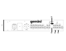
7. LOOP SECTION: Removing the jumpers from the LOOP OUTPUT
(52) and INPUT (53) jacks will activate the loop. Any device
connected to the LOOP OUTPUT (52) and INPUT (53) jacks will be
inserted into the signal path.
8. OUTPUT CONTROL SECTION: The level of the AMP OUT (48, 49)
is controlled by the MASTER (31) slide and BALANCE (30) control.
Activating the MONO (29) button (the mono LED will light) makes the
overall output mono. The BOOTH (28) control adjusts the level of the
BOOTH OUTPUT (50). HINT: The BOOTH OUTPUT is used by
some DJs to run monitor speakers in their DJ Booth. You can also
use it as a second ZONE or AMP output.
NOTE: The RECORD OUT (51) has no level control. The
level is set by the channel slides and the gain controls of
the selected channel. The tonal qualities are set by the
low, mid and high controls of that same channel.
9. TALKOVER SECTION: The purpose of the talkover section is to allow
the program playing to be muted so that the mic can be heard above
the music. The MIC/TALKOVER SWITCH (7) controls MIC 1 and MIC
2 and has three settings. When the MIC/TALKOVER SWITCH (7) is
in the bottom position, MIC 1 and MIC 2 and talkover are off. When
the MIC/TALKOVER SWITCH (7) is in the center position MIC 1 and
MIC 2 are on, the MIC INDICATOR (6) will glow, but talkover is off.
When the MIC/TALKOVER SWITCH (7) is in the top position, MIC 1
and MIC 2 and talkover will be on and the volume of all sources
except the Mic inputs are lowered by 16 dB. The TREBLE (2) and
BASS (3) controls allow you to fully adjust the tone of MIC 1 and MIC
2. MIC 1 LEVEL (5) controls the level of MIC 1. The MIC 2 LEVEL
(4) controls the level of MIC 2.
10.CUE SECTION: By connecting a set of headphones to the
HEADPHONE (45) jack, you can monitor any or all of the channels.
Press the CUE/SAMPLE ASSIGN (24) buttons for channels 1 - 4 to
select the channel or channels to be monitored and their respective
LED indicators will glow. Press the CUE/SAMPLE ASSIGN (8) button
to monitor MIC 1 and MIC2. The CUE/SAMPLE ASSIGN (8, 24)
buttons are also used to assign samples (see Sampler Operation for
more details). Press the CUE SAMPLER (35) to monitor samples.
Use the CUE LEVEL (43) control to adjust the cue volume without
effecting the overall mix. By moving the CUE PGM PAN (38) control
to the left you will be able to monitor the assigned cue signal. Moving
the control to the right will monitor the PGM (program) output. Use
the CUE SPLIT (44) button to split the signals from cue and program
so that cue will be heard in one earphone and program will be heard
in the other earphone.
11. DISPLAY: The peak hold, dual function DISPLAY (25) indicates
either the MASTER (48, 49) output left and right levels OR the
selected cue and program (premaster output) levels. You can choose
the option you want by pressing the DISPLAY (26) button.
NOTE: When the DISPLAY (25) is in the cue/program mode,
by adjusting GAIN (9), you can increase or decrease the
signal to match the other channels signal.
Sampler Operation
GENERAL INFORMATION: The PS-900 PRO Sampler uses Dynamic
RAM memory and a 12 bit microprocessor controller. The full bandwidth
results in true sound reproduction.
MEMORY INFORMATION: The PS-900 PRO comes equipped with five
MEMORY BANKS (27). The two banks marked 2 & 2 are two seconds in
length, the two banks marked 4 & 4 are four seconds in length and the
bank marked 12 is twelve seconds in length. These banks are separate
and can not be linked. You can store a different sample in each bank but
they must be recorded individually and they must be played one at a time.
SAMPLE RECORDING:
1. Put the MODE SELECTOR (34) switch into the WRITE position.
2. Select the source you want to sample from by pressing the
appropriate CUE/SAMPLE ASSIGN (24, 8) button.
3. Select the memory bank you want to record into, by pressing the
proper MEMORY BANK (27) button.
4. The PS-900 PRO comes equipped with a sampler PITCH (33)
control. To get a perfect sample, set the control to its center position
and record the sample. During playback, raising or lowering the
control will raise or lower the pitch of the sample playback. The
center position will remain as normal pitch.
HINT: You can record a sample with the PITCH (33) control in any position.
Whatever that position is will become normal sound. If you start to record a sample
with the PITCH (33) control set at minimum (this now becomes your normal pitch),
by increasing the pitch to maximum, the pitch effect will double in speed. Recording
at maximum and lowering to minimum will do exactly the opposite.