


13Soundcraft MFXi MPMi User Guide Issue 1210
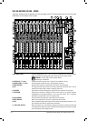
this to monitor the post-EQ signal from the channel.
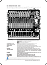
12 MIX/SUB SWITCH When this switch is up, the channel’s post-pan-pot signal is routed to the Mix (left
and right) buses. When the switch is depressed, the post-pan-pot signal is routed
to the Sub-group (left and right) buses.
13 PEAK LED This is used to indicate that the signal is close to distorting (clipping) on a specic
channel.
14 SP LED The SP LED glows when a signal is present. The feed point for the LED is post-insert,
pre-EQ.
15 INPUT CHANNEL FADER This is used to control the level fed to the Mix Bus and post-fade sends.
16 MIX OUTPUTS (XLR) Connect these to your analogue recording device, or to your amplication system.
& MONO OUT (¼” Jack)
17 SUB-GROUP OUTPUTS These outputs can be connected to a separate amplier system or to an external
(¼” Jack) processor.
18 SUB-GROUP ROUTING The sub-group mix can be routed to the main mix, in mono or stereo.
19 MASTER FADERS These faders control the overall level of the mix and sub-group outputs.
20 MAIN METERS These show the level of the mix outputs. When the master SOLO LED is lit, the meters
show the level of the selected AFL/PFL signal.
21 MONITOR OUTPUTS These are used to feed your monitoring system. This can be directly connected to
(¼” Jack) powered monitors, or indirectly via an amplier to standard monitors.
22 MONITOR CONTROL This controls the level of the signal sent to your monitoring system.
23 MONITOR SELECT SWITCH This switch selects the signal source to be monitored. Note that the 2-TK input can
be monitored also, see item 31 below.
24 PHONES CONTROL This controls the level of the signal sent to the headphones jack socket.
25 HEADPHONES (¼” Jack) Plug your headphones into this socket. Recommended headphones impedance is
32 ohms or greater.
26 AUX 1 & 2 OUTPUTS
These outputs can be used to send the channel signal to an artist’s monitors (head
(¼” Jacks)
phones/in-ear/stage monitors), external FX or secondary PA/monitor system.
27 AUX CONTROLS The rotary controls set the output levels of the two Aux Outputs. The After Fade
& AFL SWITCHES (AFL) Listen switches route their respective aux output signal to the monitor/
headphones outputs.
28 AUX 2 POST/PRE SWITCH This switch globally changes the AUX 2 feed on all the input modules to be either
post-fade or pre-fade.
29 STEREO INPUTS (¼” Jack) These two pairs of inputs can be used to connect line level stereo inputs from key-
boards, sound modules, samplers, computer based audio cards etc. These inputs
pass through a stereo channel strip, with EQ, Auxes and a Balance control. Mono
sources may be used by plugging into the left jack only.
30 2-TRACK IN
(RCA Phono)
You can connect the playback from your recording device here.
31 2-TRACK OUT Use these to control the 2 Track signal. The MONITOR switch sends the signal to the
monitor outputs and phones, whilst the TO MIX switch sends it to the main mix.
32 RECORD OUTPUTS
(RCA Phono)
You can connect these to the inputs of your recording device.
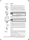
33 PHANTOM POWER Press this to globally switch the phantom power (48V) on for condenser microphones.
WARNING: Do Not apply Phantom Power before
connecting a microphone.
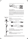
34 STEREO RETURN INPUTS This pair of inputs accept 3-pole ‘A’ gauge (TRS) jacks. Use these inputs for sources
such as keyboards, drum machines, synths or CDs. The inputs are BALANCED. Mono
sources may be used by plugging into the left jack only.
35 STEREO RETURN CONTROL This control sets the level of signal routed to the main mix busses.
36 FX BUS OUTPUT This output carries the signal from the FX bus. It could be used as a third Aux Output
if desired if the FX Processor is not needed at the time. The FX sends on the inputs
channels to the FX bus are always post-fade.
37 FX CONTROL & AFL SWITCH The rotary control regulates the signal level being fed from the FX bus to the FX
processor and to the FX BUS OUTPUT socket. The After-Fade Listen (AFL) switch
routes this post-FX-control, pre-FX signal to the monitor/headphones outputs.
38 FOOTSWITCH CONNECTOR This is used by the FX Processor, see page 33.
39 LEXICON® FX PROCESSOR See the information starting on page 33 .