


34 Soundcraft MFXi MPMi User Guide Issue 1210
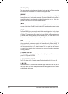
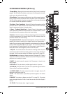
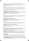
FX PROCESSOR CONTROLS (MFXi only)
1. Tempo Button - Tapping this button twice sets the Delay Time of the selected
program. The LED ashes to indicate current tempo. Can be tapped in time with
music source to synchronise the delay.
2. Store Button - Stores program modications to one of the program locations.
Press and hold for three seconds will store the preset in the current location.
The LED will ash rapidly during the store operation and then stay illuminated
for 1 second to show the operation is complete.
3. Pre Delay / Time/ Speed Knob - Controls Pre Delay of the reverbs or the rst
parameter (time or speed related) of the selected effect. The LED illuminates
when the parameter matches the stored setting.
4. Decay / Feedback/Depth Knob - Controls Decay of the reverbs or the
second parameter (feedback or depth related) of the selected effect. The LED
illuminates when the parameter matches the stored setting.
5. Variation - Controls Liveliness or Diffusion (depending on the reverb selected)
or the third parameter of the selected effect. The LED illuminates when the
parameter matches the stored setting.
6. Program Select Knob - Navigates through programs, turning to the required
program will initiate the loading of the program which take approximately 1
second. The knob can be rotated clockwise or anticlockwise and will alternate
between BANK A and BANK B every full rotation. The current bank is shown
by its illuminated LED, which ashes if the FX processor is muted. There is a
handy aide memoir of the programs printed on the front panel.
7. Clip LED – This LED illuminates when either the incoming audio or the pro-
cessed audio (within the effect processor) overloads, and causes distortion of
the signal. If this illuminates reduce the FX Master Level (item 25, page 32).
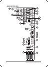
Footswitch Input (not shown on diagram, see item 28 on page 28) - Using a
single pole, momentary footswitch inserted into the MUTE FX input the effects
processor can be muted/un-muted.
8. MUTE - This switch mutes the output of the FX processor. It doesn’t mute
the PFL signal.
9. FX TO AUX 1 - This pot routes a pre-fade signal to the Aux 1-pre bus.
10. FX TO AUX 2- This pot routes a pre-fade and a post-fade signal to the Aux
2-pre and Aux 2-post busses respectively.
11. EFFECTS FADER - This fader controls the level of the signal, from the FX
processor, routed to the main mix.
12. PFL - This switch routes a post-effects processor signal to the monitor
system.
FX BUS OUT (not shown on diagram, see item 27 on page 28) - This output
carries the signal from the FX bus. It could be used as a third Aux Output if
desired.
13. ‘SP’ LED - This indicates when a signal is present.
24-BITDIGITAL
EFFECTSPROCESSOR
A:PRE-DEL
B:TME/SPD
A
B
:VARI
010
010
PFL
PK
SP
MUTE
FX
BANKA
BANKB
STORE
TEMPO
TAP
FXTO
AUX1
FXTO
AUX2
A:DECAY
B:FBK/DPTH
EFFECTS
-5
-10
-15
-20
-30
-40
0
3
4
5
7
9
10
11
1
2
6
8
12
13
S.HALL
L.HALL
V.HALL
D.HALL
S.PLT
L.PLT
V.PLT
D.PLT
ROOM
STUDIO
CHMBR
AMB
ARENA
GATED
REV
SPRING
1
2
3
4
5
6
7
8
9
10
11
12
13
14
15
S.DLY
D.DLY
T.DLY
P.DLY
M.DLY
R.DLY
CHORUS
FLANGR
PHASR
TREM/P
VIBRTO
RV/DLS
RV/DLL
PHSDEL
ROTDEL
BANKA BANKB
KARAOKE
16