


15
MASTER SECTION FEATURES
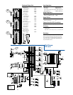
CLIP
0dB
=
0dBu
LEFT RIGHT
ZERO
LEVEL
SET
48v
dB
30
20
10
OO
40
50
5
5
U
60
10
POWER STATUS
RUDE SOLO
22
10
7
4
2
0
2
4
7
10
20
30
STEREO
MAIN MIX
PHANTOM POWER
We hope you’ve understood, if not memo-
rized, the CHANNEL STRIP FEATURES you
just read. If you’re still confused, please look
them over again before you tackle this section.
Don’t worry, it’s easy to swallow as long as you
take it a bite at a time.
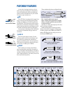
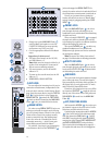
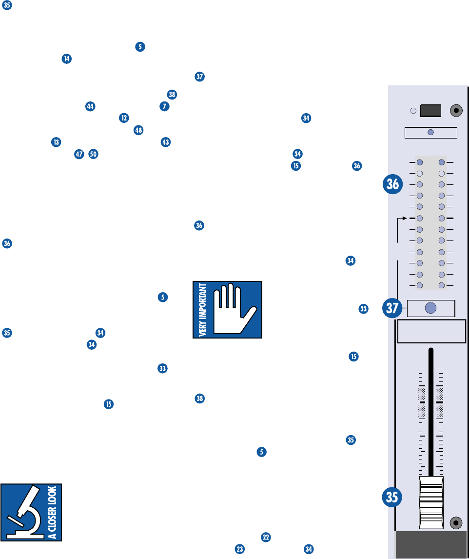
MAIN MIX FADER
As the name implies, this stereo fader con-
trols the levels of signals sent to the main
outputs: XLR and TRS
MAIN OUT
. The
TAPE OUTPUT
RCA jacks also receive the
main mix, but before the
MAIN MIX
Fader.
Signals feeding the
MAIN MIX
Fader, after
passing through the
STEREO GRAPHIC EQ
,
include:
SUB ASSIGN
,
MAIN INSERT
,
STEREO EFX RETURN 1
and
2
(including
the
EMAC EFFECTS PROCESSOR
), and
TAPE INPUT
. All assigned
SUB
Faders
and
EFX RETURN
s that are not turned
fully down will appear in the
MAIN MIX
.
The fader, set fully up, provides 10 dB of gain.
A “
U
” unity gain point is just below that. When
set fully down, the main mix is effectively
muted. This is the fader to pull down at the end
of the song when you want The Great Fade-Out.
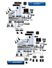
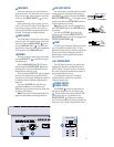
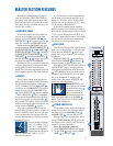
METERS
The CFX Mixer’s peak metering system is
made up of two columns of twelve LEDs each,
with thresholds ranging from –30 dB up to
“CLIP” (+22 dBu at the TRS
MAIN OUT
,
+28 dBu at the XLR
MAIN OUT
). The meters
display the main mix, post
MAIN MIX
Fader
, unless a
SOLO PFL
switch is engaged.
When a
SOLO PFL
switch is engaged,
the meters will instead display the solo infor-
mation, at unity gain (pre channel fader
).
Why, you ask? The meters, being a tool for the
engineer, must display what the engineer is lis-
tening to via the
PHONES
output.
You can get a good mix with the meter’s
peaks flashing anywhere between –20 and +10
dB. Most amplifiers clip at about +10 dB, and
some recorders aren’t so forgiving either. For
best real-world results, try to keep your peaks
between “0” and “+7.”
You may already be familiar
with “+4” (+4 dBu=1.23V)
and “–10” (–10 dBV=0.32V)
operating levels. Basically,
what determines the operat-
ing level is the relative 0 dB VU (or 0VU)
chosen for the meters.
A “+4” mixer, with a +4 dBu signal pouring
out the back, will actually display 0 dB on its
meters. A “–10” mixer, with a –10 dBV signal
trickling out, will also display 0 dB. So ... when
is 0 dB actually 0 dB? Right now!
At the risk of creating another standard,
Mackie’s compact mixers address the need of
both crowds by calling things as they are: 0 dBu
(0.775V) at the output shows as 0 dB VU on
the meters. What could be easier? (By the way,
the most wonderful thing about standards is
that there are so many to choose from.)
RUDE SOLO
This infamous flashing LED (Light Emitting
Diode) serves two purposes —- to remind you
that at least one
SOLO PFL
switch is en-
gaged, and to let you know that you’re mixing
on a Mackie.
Engaging a
SOLO PFL
switch affects
these features:
PHONES
and Meters .
No other outputs are affected in any way.
Although the “SET THE LEVELS” section of
“QUICK START” (page 5) will get your level-
setting tasks accomplished, using the meters
in
PFL SOLO
mode lets you really tune in.
Instead of one flickering LED, you can make
use of the 12-segment VU display in the
meters. How? Just engage a
SOLO PFL
switch and watch the meters.
WARNING:
SOLO
is pre-
fader and taps the channel
signal before the fader
.
If you have a channel’s
fader set well below “
U
”
(unity gain),
SOLO
won’t know that and will
send a unity gain signal to the
PHONES
output. That may result in a startling level
boost in your headphones.
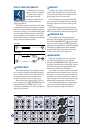
STEREO GRAPHIC EQ
This equalizer, used to shape the frequency
spectrum of the main mix, is the last thing in
the chain prior to the
MAIN MIX
Fader
and
MAIN OUT
XLR and TRS jacks.
Although there is no actual bypass switch
for the
STEREO GRAPHIC EQ
, by setting all
the sliders to zero (center) you’ll effectively
remove it from the signal path.
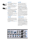
How to find and reduce feedback:
1. Set the
GRAPHIC EQ
sliders to zero (center).
2. Set the
TRIM
levels, using the
ZERO
LEVEL
or
SOLO PFL
.