


MIXER
SR24•4-VLZ PRO
SR24•4-VLZ PRO
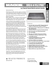
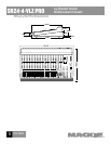
24-Channel Sound
Reinforcement Console
O F 8 P A G E S
MIXER
SR24•4-VLZ PRO
SR24•4-VLZ PRO
24-Channel Sound
Reinforcement Console
O F 8 P A G E S
www.mackie.com
16220 Wood-Red Road NE, Woodinville, WA 98072 USA
888.337.7404, fax 425.487.4337, sales@mackie.com
UK +44.1268.571.212, fax +44.1268.570.809, uk@mackie.com
ITALY +39.0522.354.111, fax +39.0522.926.208, italy@mackie.com
FRANCE +33.3.85.46.91.60, fax +33.3.85.46.91.61, france@mackie.com
GERMANY +49.2572.96042.0, fax +49.2572.96042.10, germany@mackie.com
SR24•4-VLZ PRO
™
24-Channel Sound Reinforcement Console
1
O F 8 P A G E S
MIXER
SR24•4-VLZ PRO
MIXER
SR24•4-VLZ PRO
O F 8 P A G E S
SR24•4-VLZ PRO
24-Channel Sound
Reinforcement Console
7
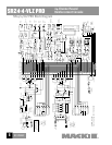
Architects’ and Engineers’ Specications
1. GENERAL CONFIGURATION. The audio mixer shall
have a free-standing frame tted with four resilient
feet suitable for tabletop placement. The frame shall
be comprised of 20 monaural input channels, 2 stereo
input channels, 4 submix output channels and 2 main
output channels. The monaural input channels shall be
capable of accepting either microphone- or line-level
signals, and shall be tted with trim, equalization, bal-
ance, and auxiliary send controls; solo, mute, and bus
assign switches; level-indicating LEDs and insert jacks.
The stereo input channels shall be capable of accept-
ing either stereo or monaural line-level signals, and
shall be tted with stereo trim, equalization, balance,
and auxiliary send controls; solo, mute and bus assign
switches; and level indicating LEDs. The submix outputs
shall each have level, pan, and “air” controls; solo and
assign switches; and a bus access insert jack. The main
outputs shall share a stereo master output fader and
shall be tted with insert jacks. Additionally, the mixer
shall include a pre-fader/post fader solo function, a
main monaural output with level control derived from the
main stereo outputs, 6 monitor/effects send outputs, 4
stereo effects return inputs with switching and control
functions, 1 stereo control room monitor output, 2 stereo
headphone outputs, 1 set of stereo tape recorder conve-
nience outputs, and 1 set of stereo tape monitor inputs.
2. POWER SUPPLY.
All necessary operating voltages for
the mixer shall be provided by an internal power supply.
3. INPUT CHANNEL CONNECTIONS. Each monau-
ral channel (1-20) shall include an XDR™ (Extended
Dynamic Range) electronically balanced microphone
input, using an XLR-3-F-type connector, accepting
nominal levels from –60 dBu to +4 dBu via a rotary Trim
control. Phantom power shall be globally controlled via
a rocker-type switch. Each monaural input channel shall
also have an electronically balanced line level input,
accommodating a nominal line level of between –10 dBV
and +4 dBu, and appearing on the rear panel as a 1/4"
TRS phone jack. Each stereo input channel shall have
left and right electronically balanced line level input,
accommodating a nominal line level of between –10 dBV
and +4 dBu, and appearing on the rear panel as 1/4"
TRS phone jacks. These jacks shall be tted with internal
switching contacts to accommodate monaural congura-
tion. Additionally, each of the monaural input channels
(1-20) shall offer an unbalanced insert connection,
appearing on the rear panel as a 1/4" TRS phone jack.
4. INPUT CHANNEL LEVEL AND ASSIGNMENT
CONTROLS AND INDICATORS. Each monaural input chan-
nel shall be equipped with a preamplier gain control,
a solo switch, a mute switch, three bus assignment
switches, and a stereo pan control. Each stereo input
channel shall be equipped with a dual preamplier gain
control, a solo switch, a mute switch, three bus assign-
ment switches and a stereo balance control.
5. INPUT CHANNEL EQUALIZATION. Each monaural
input channel shall be equipped with an equalization
function. The equalizer shall have three sections: a low-
frequency shelving equalizer with the knee set at 80 Hz
and a range of +15 dB; a mid-frequency peaking equal-
izer with a center frequency sweepable from a range of
100 Hz to 8 kHz, and a range of +15 dB; and a high-fre-
quency shelving equalizer with the knee set at 12 kHz
and a range of +15 dB. Each stereo input channel shall
be equipped with a stereo equalization function. The
equalizer shall have four sections: a low-frequency shelv-
ing equalizer with the knee set at 80 Hz and a range of
+15 dB; a low-mid-frequency peaking equalizer centered
at 800 Hz and a range of +15 dB; a high-mid-frequency
peaking equalizer centered at 3.5 kHz and a range of
+15 dB; and a high frequency shelving equalizer with the
knee set at 12 kHz and a range of +15 dB.
6. INPUT CHANNEL AUXILIARY SENDS. Each mixer
input channel shall have 6 monaural auxiliary send con-
trols. Two auxiliary send controls shall be xed as pre-
fader sends; two shall be xed as post-fader sends; and
two shall be switchable between pre-fader and post-fad-
er. All auxiliary sends shall be post-mute switch.
7. MAIN OUTPUT CONNECTIONS. The mixer shall have
electronically balanced, line-level left and right main
outputs, appearing on male XLR-3 type connectors and
impedance balanced on 1/4" phone TRS jacks on the rear
panel. Additionally, the main buses shall offer left and
right unbalanced insert connections, appearing on
the
rear panel as 1/4" phone TRS jacks. Further, there shall be
a main, electronically balanced, monaural output derived
from the main stereo output, appearing as a male XLR-3
type connector on the rear panel. There shall be an output
level control to adjust the main monaural output level.
8. OTHER OUTPUT AND MONITORING CONNECTIONS.
The mixer shall have the following impedance balanced
line-level connections, appearing as 1/4" TRS jacks on
the rear panel: submix bus outputs 1-4, also wired in
parallel respectively to submix outputs 5-8; left and right
control room monitor outputs, left and right tape monitor
outputs, left and right tape monitor inputs. For conve-
nience, the left and right main outputs (unbalanced) and
the left and right tape monitor inputs shall also appear
as RCA phono jacks on the rear panel. There shall also be
two stereo headphone outputs on the rear panel of the
mixer, carrying the control room monitor signals at levels
and impedances proper for headphones. Each head-
phone output connection shall be a stereo 1/4" jack.