


MIXER
SR24•4-VLZ PRO
SR24•4-VLZ PRO
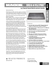
24-Channel Sound
Reinforcement Console
O F 8 P A G E S
MIXER
SR24•4-VLZ PRO
SR24•4-VLZ PRO
24-Channel Sound
Reinforcement Console
O F 8 P A G E S
www.mackie.com
16220 Wood-Red Road NE, Woodinville, WA 98072 USA
800.898.3211, fax 425.487.4337, sales@mackie.com
UK +44.1268.570.808, fax +44.1268.570.809, uk@mackie.com
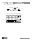
SR24•4-VLZ PRO
™
24-Channel Sound Reinforcement Console
1
O F 8 P A G E S
MIXER
SR24•4-VLZ PRO
MIXER
SR24•4-VLZ PRO
O F 8 P A G E S
SR24•4-VLZ PRO
24-Channel Sound
Reinforcement Console
8
Electronic les for this product available at:
www.mackie.com/installed
This Specication Sheet SR24VLZPRO_SS.PDF
Owner/Operator’s Manual SRVLZPRO_OM.PDF
Part No. 0003711 Rev A2 9/04
9. OUTPUT AND MONITORING CONTROLS AND SWITCHES.
The mixer shall include one linear fader control for gain
adjustment of main L/R outputs, covering a range from
innite attenuation to +10 dB above unity gain. A tape
monitor switch shall alternately select either the main L/R
outputs or the signal at the tape inputs as the source for
the control room and headphones monitoring circuits.
There shall be a stereo dual-channel rotary control for gain
adjustment of the control room and headphone monitor
output. The mixer shall have a stereo dual-channel control
for adjustment of the monitoring level of the internal solo
signals, and a light to indicate channel solo condition.
The solo system shall be capable of switching between
PFL (pre-fader listen) and AFL (after-fader listen––solo in
place) operation.
10. OUTPUT METERING. The mixer frame shall include
two 13-segment LED meters each displaying a signal range
from –40 dBU to +10 dBu, each with an additional LED
indicating mixer clipping level at +22 dBu. The meters
shall monitor the main left and right output channels;
alternately, the meters shall monitor the tape return sig-
nals when the tape monitor switch is depressed; or, the
soloed input channel signals when the solo switch is
depressed.
11. AUXILIARY SEND CONNECTIONS. The mixer shall
include impedance balanced, line-level outputs from the
six auxiliary send buses, appearing on the rear panel as
1/4" TRS phone jacks.
12. AUXILIARY RETURN CONNECTIONS. The mixer shall
include 4 stereo auxiliary return inputs. Each auxiliary
return shall have a left and a right balanced line-level
input, accommodating a nominal line level of between
–10 dBu
and +4 dBu, and shall appear on the rear panel
as 1/4" TRS phone jacks. The jacks shall be tted with
internal switching contacts to accommodate monaural
conguration.
13. AUXILIARY RETURN CONTROLS AND SWITCHES. The
mixer shall include 4 dual-channel auxiliary return gain
controls, each feeding the main stereo buses. Auxiliary
returns 1-2 shall have their signals assignable to auxiliary
send buses 1 and 2, respectively, through rotary level con-
trols. Auxiliary return 4 shall be assignable to three differ-
ent pairs of destinations, feeding either the main left and
right buses or the submix buses.
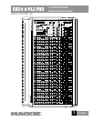
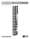
14. PHYSICAL CONFIGURATION. The mixer shall have
a steel chassis frame painted grey-black and designed to
rest on a horizontal surface. The SR24•4-VLZ PRO’s dimen-
sions shall be 6.1" (155mm) high by 31" (787mm) wide by
19.2" (487mm) deep.
15. SPECIFICATIONS. In addition to specications
previously cited, the mixer shall meet or exceed the fol-
lowing specications. Frequency response, microphone
input to any output, 20 kHz to 60 kHz, +0 dB/ –1 dB;
Total Harmonic Distortion (THD), any input to any output,
1 kHz @ +14dBu, 0.004%; Equivalent Input Noise (EIN),
microphone input to insert send, –129.5 dBm; Common
Mode Rejection (CMR), microphone input to insert send,
maximum gain, 1 kHz, better than 90 dB; Typical Main
Output noise, all channels assigned, odd channels panned
left, even channels panned right, all faders down –94.7
dBu; Signal to Noise ratio, ref +4 dBu operating level, 90
dB; Attenuation, ref. 0 dB @ 1 kHz, Main Mix level con-
trol down, –85 dBu; Channel Mute engaged, –84 dBu;
Channel Gain control down, –83 dBu; Input impedance,
microphone inputs, 1.5 kΩ; Channel Insert return, 2.5 kΩ;
all other inputs, greater than 10 kΩ; Output impedance,
Tape Out, 1.1 kΩ; All other outputs, 120Ω.
16. DESIGNATION. The mixer shall be a Mackie
SR24•4-VLZ PRO.
LOUD Technologies continually engages in research related to product improvement. New material,
production methods, and design renements are introduced into existing products without notice as
a routine expression of that philosophy. For this reason, any current LOUD Technologies product may
differ in some respect from its published description, but will always equal or exceed the original
design specications unless otherwise stated. ©1999–2004 LOUD Technologies Inc. All rights
reserved. Mackie and the “Running Man” gure are registered trademarks of LOUD Technologies Inc.