


18
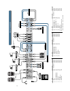
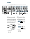
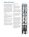
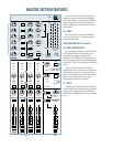
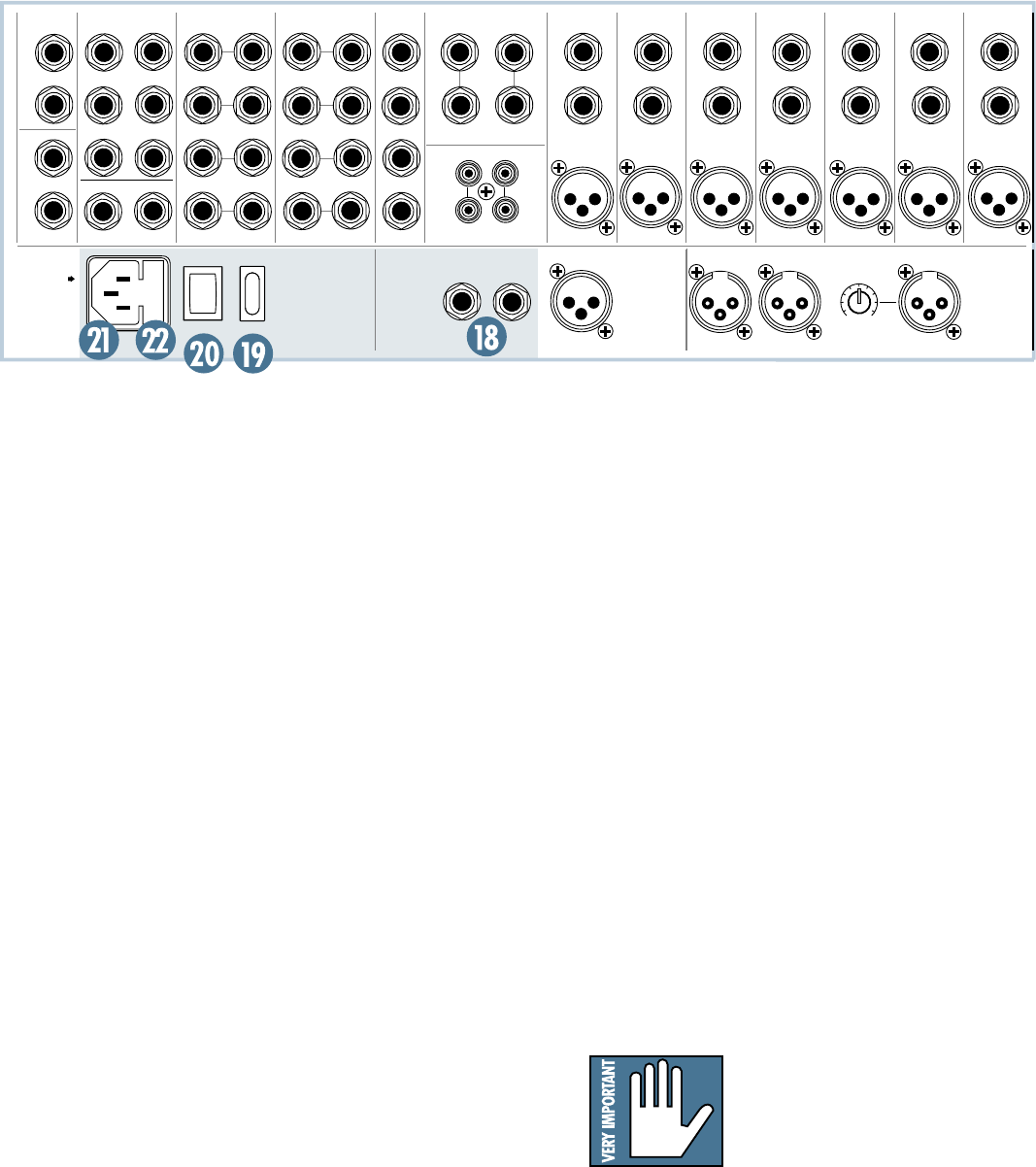
18. PHONES
The stereo signal from each of these identi-
cal outputs is a high-current version of the
signal from CONTROL ROOM OUT (11). Con-
nect TRS headphones to either or both jacks.
The stereo signal at these jacks is the same
as the MAIN OUTS (12) (16), except when
SOLO (39) or TAPE RETURN TO PHONES/C-R
(69) is engaged. Its level is independently con-
trolled by PHONES/C-R LEVEL (70).
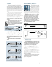
TRS stereo wiring:
Tip = left, ring = right, sleeve = shield
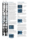
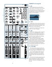
19. PHANTOM
Engage this switch to provide phantom
power to all the MIC (1) input jacks. All of the
XLR mic inputs, except TALKBACK MIC (17),
are capable of simultaneously providing phan-
tom power. Phantom power is required to
operate most condenser microphones (some
condenser microphones are battery-powered).
+48VDC phantom power is delivered to pins 2
and 3 of the XLR connectors.
For dynamic, ribbon or tube mics that do
not require phantom power, leave this switch
off. If both condenser and dynamic mics are
used, turn the switch on. Phantom power will
not hurt most dynamic mics. If unsure, check
the microphone’s user manual.
Caution: Turn all output levels down before
operating this switch to avoid the possibility of
a “pop” in the speakers.
Caution: Connecting an external line-level
device to an XLR input connector with the
phantom power activated could damage that
device. Use the LINE IN (2) or STEREO LINE
IN (4) jacks for connecting line-level signals.
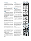
20. POWER
The POWER switch is located on the rear
panel, adjacent to the AC RECEPTACLE (21).
Push in the top side of the switch to turn on,
this connects the mixer to main AC power. The
POWER (55) LED in the top right corner of the
console, will glow in confirmation.
To turn the mixer off, push the switch the
other way. Note: turning off the switch does not
remove all power from the mixer. To remove all
power, the power cord must be disconnected
from the power source.
21. AC RECEPTACLE
Connect the supplied AC linecord into this
IEC socket to provide AC power to the Mixer.
Plug the cord into a suitable AC outlet; prop-
erly grounded and capable of delivering
adequate current.
Replacement AC linecords are widely avail-
able at any office or computer supply store.
22. FUSE INSIDE
An AC power fuse is located in a tiny slide-
out compartment inside the AC RECEPTACLE
(21). It’s a good idea to carry spare fuses.
Always remove the
power cord before changing
the fuse.
Always use the correctly
rated fuse for your specific
mixer:
Use the fuse value shown on the rear panel
of your mixer, near the fuseholder.
INSERT INSERT INSERT INSERT INSERT INSERT INSERT
MIC 20
TAPE OUTTAPE IN
TALK BACK
MIC
R
R
R
(MONO)
4
L
L
L
3
2
1
L
CONTROL ROOM OUTMAIN INSERTS
3
3
4
2
3
1
1
LL
R
RR
L
24
23 21
22
20
MIC 19
19
LINE IN
(BAL OR UNBAL)
LINE IN
(BAL OR UNBAL)
LINE IN
(BAL OR UNBAL)
LINE IN
(BAL OR UNBAL)
LINE IN
(BAL OR UNBAL)
LINE IN
(BAL OR UNBAL)
LINE IN
(BAL OR UNBAL)
MIC 18
18
MIC 17
17
MIC 16
16
MIC 15
15
MIC 14
14
RIGHT
MAIN OUT
LEFT
MAIN OUT
MONO
MAIN OUT
OUTPUT
LEVEL
PHONES
2
PHONES
1
OFF
POWER
ON
OFF
PHANTOM
ON
MONO MONO
PIN 2 = HOT
PIN 3 = COLD
FUSE INSIDE
CAUTION:
TO REDUCE
THE RISK OF FIRE, REPLACE
WITH THE SAME TYPE FUSE
AND RATING
OO
+6
MAIN
BALANCED
OUTPUTS
R
R
L
L
AUX SENDS
(BAL OR UNBAL)
STEREO AUX RETURNS
(BAL OR UNBAL)
SUB INSERTS
(BAL OR UNBAL)
6
2
5
14
R
R
L
R
L
7
8
6
5
SUB OUTS
(BAL OR UNBAL)
4
2
MAIN OUTS
(BAL OR UNBAL)
(BAL OR UNBAL)
X
D
R
M
I
C
P
R
E
X
D
R
M
I
C
P
R
E
X
D
R
M
I
C
P
R
E
X
D
R
M
I
C
P
R
E
X
D
R
M
I
C
P
R
E
X
D
R
M
I
C
P
R
E
X
D
R
M
I
C
P
R
E