


ENGLISH
4
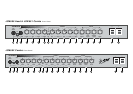
13) Treble Control
Controls the upper or treble frequencies in the
tone of the Overdrive channel.
Please Note
The Tone Controls are interactive and
adjusting one can effect the relative amounts
of the others. Experimentation is the best way
of finding your own personal favourites.
14) Parallel Effects Mix Control
Governs the amount of effected signal in the
overall tone when used in conjunction with
external effects through the parallel loop (see
items 3 and 4 of the JCM 600 rear panel
functions).
15) Clean Reverb
Controls the amount of Reverb on the Clean
channel.
16) Overdrive Reverb
Controls the amount of Reverb on the
Overdrive channel.
17) Volume
Controls the overall volume of the combo.
18) Standby Switch
Controls the H.T. supply to the valves and
allows the valves to remain heated when not
in use.
19) Power Switch
On / Off Switch for mains power to the
amplifier.
Please Note
To prolong the life of the valves it is always
advisable to switch on the Mains Power
Switch (item 19) about 2 minutes before
switching on the Standby (item 18).
This allows the valves to heat up to full
working temperature before use. On
switching off, the Standby should always be
switched before the Power Switch.
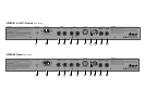
1) Mains Fuse
Protects the amplifier and mains supply in the
event of a fault.
Check the label on the back of the amp for the
correct value. Always replace fuses with the
correct type and rating. It is a wise precaution
to always carry spares.
2) Mains Input
Connects the amplifier to the mains power
supply.
3) Parallel FX Loop Return Jack
Jack socket for connection from the output of
an external effects processor.
Please Note
A parallel FX Loop is best suited for use with
external effects processors which require a
certain amount of dry or uneffected signal in
the overall tone. Time based effects such as
Delay and Chorus are typical examples of the
effects best suited to this type of Loop.
4) Parallel FX Loop Send Jack
Jack socket for connection to the input of an
external effects processor.
5) Series FX Loop Return Jack
Jack socket for connection to the output of an
external effects processor.
6) Series FX Loop Send Jack
Jack socket for connection to the input of an
external effects processor.
Note: The Series Loop is best suited to effects
that require no dry signal such as
Compressors or Graphic Equalisers.
7) D.I. Output
The JCM 600’s D.I. Out is switchable
between a speaker Emulated signal (pre the
power amp), and a non Emulated (post the
power amp ) signal.
The Emulated Output captures the tonality of
Vintage loudspeakers like no other D.I.
furthermore this output is unaffected by the
Master Volume controls therefore allowing
the JCM 600’s output to be turned off whilst
still providing silent recording facilities.
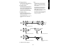
The D.I. Output is via an XLR type connector
which allows this system to be run into either
(a) a line level balanced input (b) a line level
unbalanced input or (c) a low level
unbalanced input.
Please Note
Refer to the JCM 600 XLR Out diagrams
(Below) for correct connections.
8) Pre/Post Switch
Allows Line Out selection between a speaker
Emulated signal (pre the power amp) and
non-emulated (post the power amp).
JCM 601, 602 & JCM600 Head
Rear Panel Functions
✪