


PAGE 12 — MTX40SF RAMMER • OPERATION AND PARTS MANUAL — REV. #0 (11/28/12)
COMPONENTS
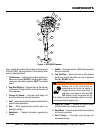
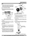
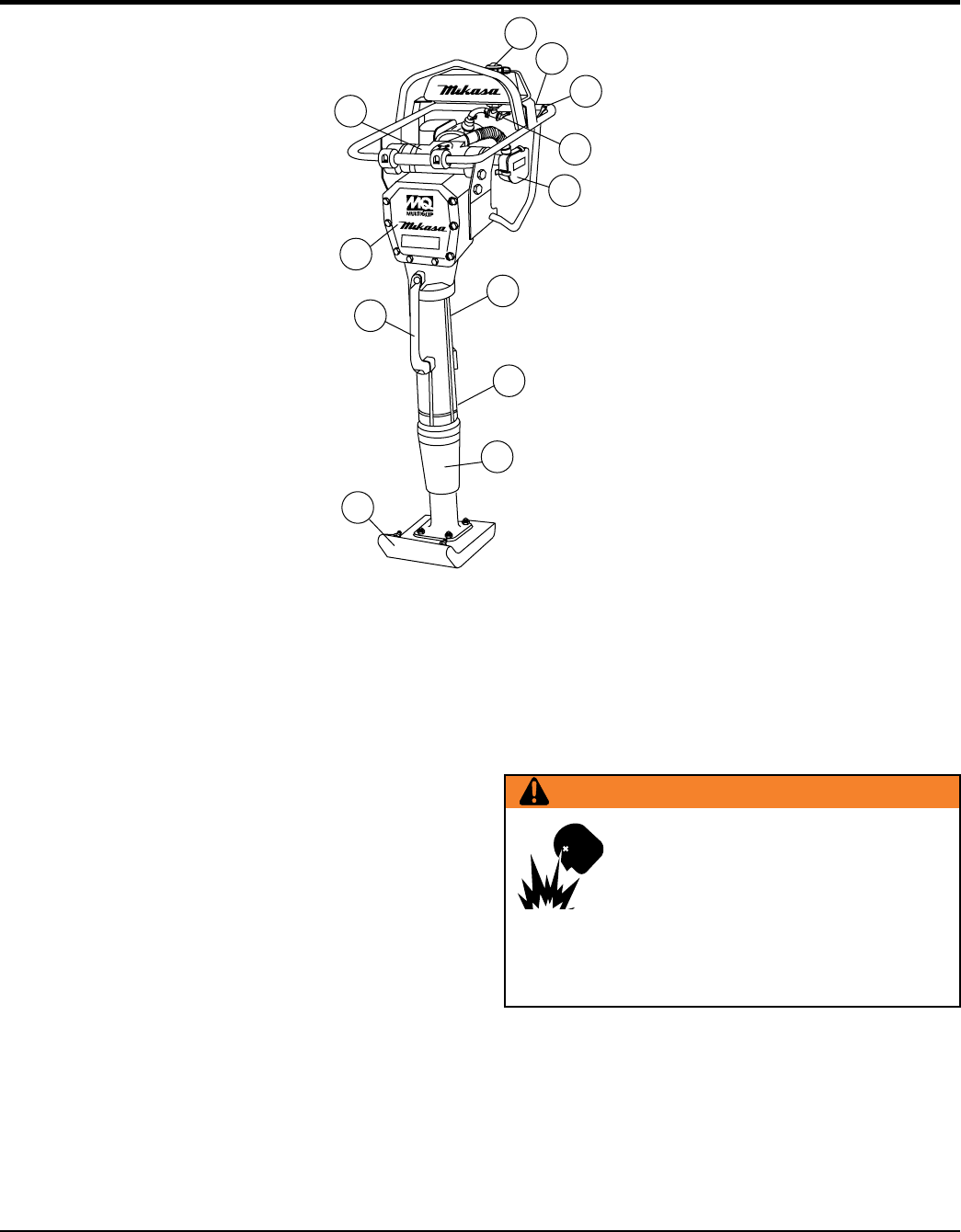
Figure 1. MTR40SF Rammer
5
10
4
6
3
8
7
1
2
9
11
11
Figure 1 shows the location of the controls and components
for the MTR40SF Tamping Rammer. The functions of each
control is described below:
1. Throttle Lever — Used to adjust engine speed (rpm).
Move lever forward (SLOW) to reduce engine speed,
move lever back toward operator (FAST) to increase
speed.
2. Fuel Shut-Off Valve — Supplies fuel from the fuel tank
to the engine. To begin fuel flow, move the fuel shut-off
valve downward.
3. Primary Air Cleaner — Pre-cleans (first stage) dirt
and other debris from entering the engine.
4. Foot — Laminated wood with tempered steel plate for
superior shock absorption.
5. Grip — When transporting the rammer, carry it by
griping the handle.
6. Nameplate — Displays information regarding the
rammer.
7. Handle — To operate rammer GRIP handle assembly
firmly on both sides.
8. Fuel Tank/Cap — Remove this cap to add unleaded
gasoline to the fuel tank. Make sure cap is tightened
securely. DO NOT over fill.
9. Engine Air Cleaner — Prevents dirt (second stage)
and other debris from entering the engine.
10. Dust Sleeve — Prevents dust and debris from entering
into the spring cylinder.
11. Zerk Fittings — Lubricates main springs and
crankcase bearings.
WARNING
Adding fuel to the tank should be
accomplished only when the engine is
stopped and has had an opportunity to
cool down. In the event of a fuel spill, DO
NOT attempt to start the engine until the
fuel residue has been completely wiped up, and the
area surrounding the engine is dry.