


PAGE 14 — MTX40SF RAMMER • OPERATION AND PARTS MANUAL — REV. #0 (11/28/12)
INSPECTION
This section is intended to assist the operator with the
inspection of the rammer. It is extremely important that
this section be read carefully before attempting to operate
the rammer.
DO NOT use your rammer until this section is thoroughly
understood.
Check all nuts, bolts fasteners for tightness. Retighten
as necessary.
Clean any dirt from the recoil starter and engine cooling
fins. Wipe the entire rammer clean before operating.
Replace any missing or damaged Safety Operation
decals. It is extremely important that this section be read
carefully before attempting to operate the rammer. DO
NOT use your rammer until this section is thoroughly
understood.
Prior to Operation
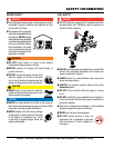
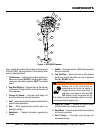
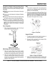
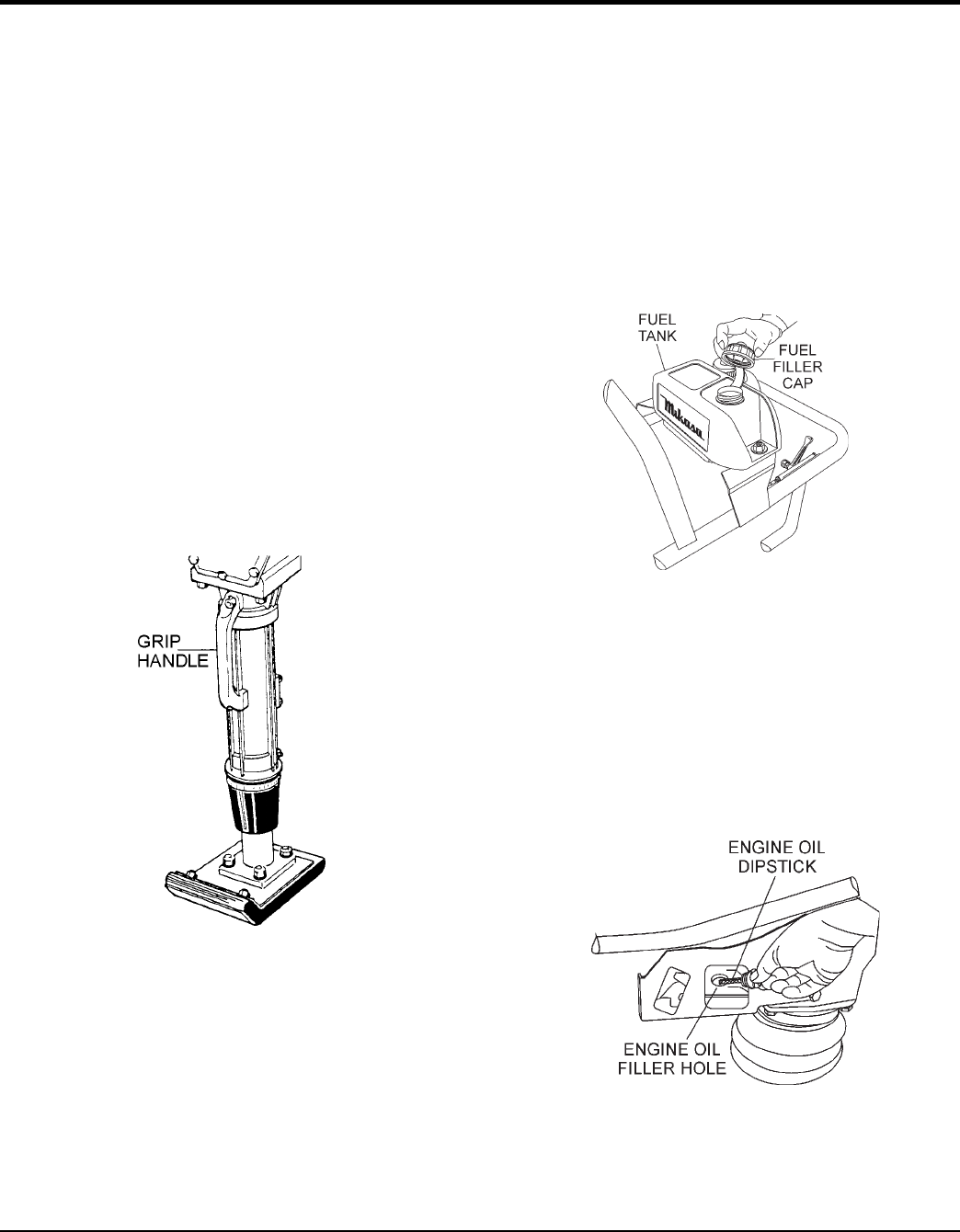
1. When transporting the rammer, carry it by the grip
handle located on the body (Figure 3).
Figure 3. Grip Handle
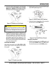
Main Spring and Crankcase Lubrication
1. There are 2 grease fittings (Figure 18) that require
lubrication of the main springs. Lubricate these fittings
as outlined in the maintenance section of this manual.
2. There are 2 grease fittings (Figure 19) that require
lubrication of the crankcase. Lubricate these fittings as
outlined in the maintenance section of this manual.to
replenish it often (Figure 5).
Fuel
1. This rammer is equipped with a two-cycled gasoline
engine. Use only unleaded gasoline. High test ethyl
gasoline is not recommended.
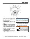
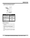
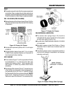
2. If fuel is low, remove the fuel filler cap (Figure 4) and
fill with onlyunleaded gasoline. Motor fuels are highly
flammable and can be dangerous if mishandled. DO
NOT smoke while refueling. DO NOT attempt to refuel
the rammer if the engine is hot or running.
Figure 4. Fuel Tank
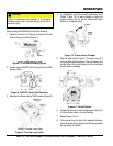
Engine Oil Check
1. To check the engine oil level, place the rammer on
secure level ground with the engine stopped.
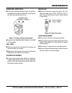
2. Remove the filler cap/dipstick from the engine oil filler
hole (Figure 5) and wipe it clean.
Figure 5. Engine Oil Dipstick
3. Insert and remove the dipstick without screwing it into
the filler neck. Check the oil level shown on the dipstick.
PAGE 14 — MTR40SF RAMMER — OPERATION AND PARTS MANUAL — REV. #5 (11/01/11)
Figure 3. Grip Handle
Prior to Operation
1. When transporting the rammer, carry it by the grip handle
located on the body (Figure 3).
Fuel
1. This rammer is equipped with a two-cycled gasoline engine.
Use only unleaded gasoline. High test ethyl gasoline
is not
recommended.
2. If fuel is low, remove the fuel filler cap (Figure 4) and fill with
only
unleaded
gasoline. Motor fuels are
highly flammable
and can be dangerous if mishandled. DO NOT smoke while
refueling.DO NOT attempt to refuel the rammer if the engine
is
hot!
or
running
.
Figure 4. Fuel Tank
This section is intended to assist the operator with the
inspection
of the
MTR40SF
Tamping Rammer.
It is extremely important that
this section be
read carefully
before attempting to operate the
rammer.
DO NOT use your rammer until this section is thoroughly
understood.
Inspection
Check all nuts, bolts fasteners for tightness. Retighten as
necessary.
Clean any dirt from the recoil starter and engine cooling fins.
Wipe the entire rammer clean before operating.
Replace any missing or damaged Safety Operation decals.
Engine Oil Check
1. To check the engine oil level, place the rammer on secure
level ground with the engine stopped.
2. Remove the filler cap/dipstick from the engine oil filler hole
(Figure 5) and wipe it clean.
Figure 5. Engine Oil Dipstick
3. Insert and remove the dipstick without screwing it into the filler
neck. Check the oil level shown on the dipstick.
4. If the oil level is low (Figure 6), fill to the edge of the oil filler
hole with the recommended oil type (Table 3). Maximum oil
capacity is .079 gallons (0.3 liters).
Main Spring and Crankcase Lubrication
1. There are 2 grease fittings (Figure 18) that require lubrica-
tion of the main springs. Lubricate these fittings as outlined
in the maintenance section of this manual.
2. There are 2 grease fittings (Figure 19) that require lubrica-
tion of the crankcase. Lubricate these fittings as outlined in
the maintenance section of this manual.
INSPECTION
DO NOT attempt to operate the Tamping
Rammer until the Safety, General
Information and Inspection sections of
this manual have been
read and
thoroughly understood
.
CAUTION