


WM63-SERIES MIXER • OPERATION AND PARTS MANUAL — REV. #0 (069/27/12) — PAGE 15
COMPONENTS
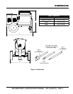
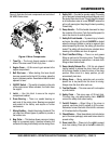
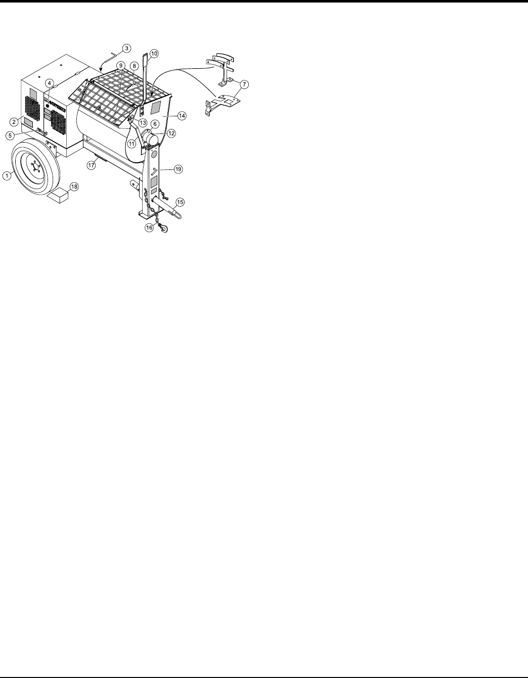
Figure 4 illustrates the basic components and controls of
the WM63 Series mixer.
Figure 4. Mixer Components
1. Tires Ply — The tire ply (layers) number is rated in
letters. This mixer uses 13-inch 4-ply tires.
2. Engine Cover — Lift this cover to gain access to the
engine compartment.
3. Belt Slip Lever — When starting, this lever should
be move upward and to the left. For mixing, place the
lever in the down position. See attached decal located
adjacent to lever.
4. ON/OFF Switch — This switch is located on the side
of the engine cover. When activated, it will shut down
the engine.
5. Latch — Use this latch to secure the engine
compartment cabinet.
6. Drum Bearing — There is a sealed bearing on
each end of the mixing drum. Bearings are packed
and sealed at the factory and require no further
maintenance.
7. Mixing Paddles — Used in the mixing of material. This
unit uses four different types of paddles to provide a
fast uniform mix.
8. Bag Cutter — This feature allows compound mixing
bags to be opened easily, therefore allowing the
contents of the bag to fall directly into the mixing drum.
9. Safety Grill — Provided for operator safety. This safety
grill is designed to keep hands and solid objects out of
the mixing drum when in use. This grill should be closed
at all times when mixer is in use. DO NOT remove the
grill or grill opening bar. Keep the grill clean by washing
it down daily.
10. Dump Handle — Pull this handle downward to dump
the contents of the drum. Push the handle upward to
return the drum to its vertical position.
11. Safety Grill Lock Handle — To prevent injury to hands
and arms, the safety grill should ALWAYS be locked
when the mixing of plaster or mortar is required. Also
when transporting the mixer, the safety grill should be
locked. The safety grill should only be unlocked when
cleaning of the blades and drum is required.
12. Pivot Point/Zerk Fitting — There is a zerk grease
fitting on each end of the mixing drum. These fittings
lubricate the dumping mechanism. Lubricate both
fittings at least twice a week.
13. Dump Handle Release Pin — Pull this pin outward
(spring loaded) to release the drum, then pull down
on the dump handle to place the drum in the dump
position. When drum is in dump position, pin will
automatically lock drum.
14. Mixing Drum — Mixing materials such as mortar,
plaster are to be placed into this drum for mixing.
Always clean the drum after each use.
15. Tow Bar/Coupler — This mixer uses a 2-inch coupler
or pintle towbar.
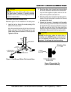
16. Safety Chain — This mixer uses a 3/16-inch thick,
72-inches long, zinc-plated safety chain. ALWAYS
connect the safety chain when towing.
17. Forklift Pockets — When lifting of the mixer is
required, use these fork lift pockets to lift the mixer.
Remember to insert the forks of the forklift a minimum
of 24 inches into the lift pockets.
18. Chock Blocks — Place these blocks (not included as
part of the mixer package) under each mixer wheel to
prevent rolling.
19. Drum Latch Pin — Place pin to the right to prevent
drum from rotating. Place pin to the left to rotate (tilt)
drum.