


WM63-SERIES MIXER • OPERATION AND PARTS MANUAL — REV. #0 (069/27/12) — PAGE 29
MAINTENANCE (MIXER)
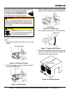
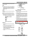
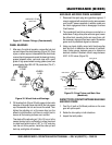
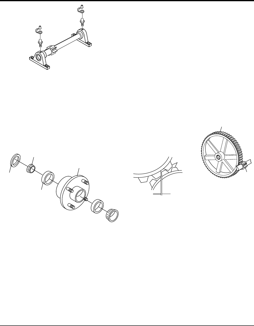
Figure 31. Grease Fittings (Countershaft)
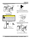
WHEEL BEARINGS
1. After every 3 months of operation, remove the hub dust
cap and inspect the wheel bearings (Figure 32). Once
a year, or when required, disassemble the wheel hubs
remove the old grease and repack the bearings forcing
grease between rollers, cone and cage with a good
grade of high speed wheel bearing grease (never use
grease heavier than 265 A.S.T.M. penetration (“No. 2.”).
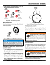
Figure 32. Wheel Hub and Bearings
2. Fill the wheel hub (Figure 32) with grease to the inside
diameter of the outer races and also fill the hub grease
cap. Reassemble the hub and mount the wheel. Then
tighten the adjusting nut, at the same time turn the
wheel in both directions, until there is a slight bind to
be sure all the bearing surfaces are in contact.
Then back-off the adjusting nut 1/6 to 1/4 turn or to the
nearest locking hole or sufficiently to allow the wheel
to rotate freely within limits of .001” to .010” end play.
Lock the nut at this position. Install the cotter pin and
dust cap, and tighten all hardware.
GREASE FITTING
AND CAP
WHEEL
HUB
BEARING
CUP
BEARING
CONE
OIL
SEAL
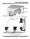
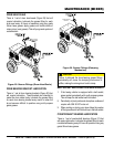
MAIN GEAR AND DRIVE PINION ALIGNMENT
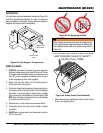
1. Disconnect the spark plug wire (gasoline engines). If
mixer is equipped with an electric motor remove power
cord from AC power receptacle. In addition make sure
the clutch engagement lever is disengaged to relieve
V-belt tension.
2. The countershaft and drive pinion are mounted on a
slotted base. To align drive pinion with main gear, loosen
the pillow block mounting bolts and move them until
the necessary alignment has been made. Remember
gears must be paralleled aligned not skewed.
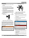
3. Using your hand, slightly move (rock) the drive pulley
back and forth to determine the amount of backlash.
Insert feeler gauge between gears to determine
backlash distance. Backlash should range between
0.007- 0.012 inches (Figure 33).
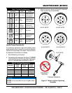
Figure 33. Drive Pinion and Main Gear
(Backlash)
INSPECT TOOTH CONTACT BETWEEN MAIN GEAR
AND DRIVE PINION
1. Coat 3 or 4 teeth at 3 different positions on the main
gear with yellow paint.
2. Rotate the drive pulley in both directions.
3. Inspect the tooth pattern.
MAIN GEAR
DRIVE
PINION
MAIN GEAR
PINION GEAR
GEAR TEETH
0.007 - 0.012 INCHES
(MAX. BACKLASH)