


3
opeRaTIon
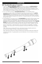
401x QUAD Receiver
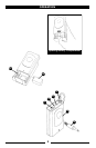
1. Powering the Receiver
Plug the 16V
AC/DC ADAPTER (1) provided into the DC INPUT JACK (11) on the back of the receiver.
Then plug the power supply into an AC outlet. [Note: Any 16V DC source with 800mA capability
can also be used.]
Turn
VOLUME CONTROL (6) for all four channels counterclockwise to mimimum located on the front
of the receiver. Once the receiver is connected to a power source, press the
POWER SWITCH (3) to
ON position. The
POWER ON LED (4) indicator will light up.
The
TX LED INDICATOR (7) on the front panel of the receiver will not light up until one or more of the
four channels is receiving a signal from your system’s transmitter.
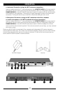
2. Antennas
The
ANTENNAS (2) assembly consists of two antennas. Connect antennas into the ANTENNA
JACKS (5)
on the front of the receiver. Extend the antennas fully to obtain maximum range.
Position
ANTENNAS (2) at45degreesfromthehorizontal;90degreesfromeachother.Formaximum
range,itisalwaysbesttomaintainalineofsight(noobstructions)betweenthereceiverantennas
and the transmitter whenever possible.
3. Mute (Squelch) Adjustment
In normal operation, the
MUTE CONTROL (9) should be set fully counterclockwise to the factory preset
minimum RF level of 1μV for maximum sensitivity. Doing so sets each receiver for maximum range.
However,inareasofhighRFactivity,themute(orsquelch,asitissometimescalled)mayneedto
beadjustedtocompensatefortheadverseconditionsinaparticularlocation.If,withthetransmitter
off,itscorrespondingLEDonthereceiverfrontpanelickersorstayson,the
MUTE CONTROL (9)
should be turned clockwise until the LED extinguishes. For each of the four channels, when the
Muteisproperlyadjusted,thecorrespondingLEDwilllightonlywhenthesystem’stransmitteris
turned on. Turning the
MUTE CONTROL (9) too far clockwise will result in reduced range, but yield a
quietersignalduringdropoutsorattheendoftheoperatingdistancerange.
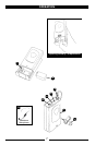
4. Connecting the Audio Output
The output stage of each channel and the separate four channels mixed output of the 401X QUAD
areallconguredforadjustableunbalancedLINEandxedbalancedXLRlineormicrophoneaudio
outputs.Theadjustableunbalanced¼”mixoutisalowlevelLINEwithanoutputimpedanceof
600 ohms. The individual fixed level balanced XLR out can be configured as high level line out with
11k ohms output impedance or microphone level out with a 600 ohms load impedance.
For each channel you wish to use, insert an audio cord with a balanced female XLR plug into its
AF OUTPUT (10)jackonbackofthereceiver.Plugtheotherendofeachcordintoyouramplier,effect
ormixingboard.Adjustvolumeonyourmixingboardsothatnoaudiodistortioninpresentwhen
amp or mixer is set at its usual level. [Note: To prevent possible undesired noises during use, leave
the volume controls of unused channels (with the corresponding transmitter off) turned off in the
amp or mixer. The audio should only be “live” if the transmitter is on.]
Ifyouwanttousethe401XQUADasitownmixer(youramplier,effectormixingboardshould
have12dBormoregainselecton),youcanconnecttothe
MIX AF OUTPUT (8) which provides a
mixed line output of up to all four channels, with the relative volume of each channel in the mix
determined by that channel’s
VOLUME CONTROL (6).