


4
UHF-24 RECEIVER
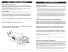
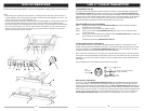
Rack-mounting the Receiver
There are two options available for rackmounting the UHF-24 Dual Channel Receiver: single or
side-by-side with another UHF-24 receiver.
a. Single mounting: Remove the
SIDE MOUNT CLIPS (1)
from each side of the receiver and
slide in the optional
ERM-3 RACK EARS
(2)
.
b. Side-by-side double mounting: After removing the
SIDE MOUNT CLIPS (1)
from each side
of the receivers, join the two receivers with the
EJC-3 JOINING CLIPS (3)
and slide in the
ERM-33 EARS (4)
.
(Note: Do not mount the receiver in a rack directly above an amplifi er or other source of high heat.
This could degrade the performance of the UHF-24 receiver. Always ensure adequate airfl ow and
heat dissipation in any rack confi guration.)
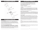
Antennas
The UHF-24 receiver is equipped with
DUAL TELESCOPIC RETRACTABLE ANTENNAS (5)
.
These should be extended fully to obtain maximum range. The optimal antenna positions are 45
degrees from the receiver and 90 degree from each other. For maximum range, it is always best
to maintain a line of sight (no obstruction) between the receiver antennas and the transmitter at all
time whenever possible.
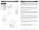
Powering the Receiver
Powering the receiver by plugging the provided
DC ADAPTOR (15VDC/0.4A) PLUG
(15)
into the
DC INPUT JACK (14)
on the back of the receiver. Then plug the adapter into an AC outlet.
(Note:
Any 15VDC/0.4A capacity AC/DC adapter can also be used.)
Turn
VOLUME CONTROLS (10)
of
all channels to counter-clockwise for minimum setting. Once the receiver is connected to a power
source, push the
POWER SWITCH (
7)
to the ON position. The
POWER LED (6)
will light up. The
received signal
CH. A OR B LEDs (8)
and
5-SEGMENT AF LED (9)
indicators on the front panel of
the receivers will not light up at this time, until one or more of the two channels is receiving a signal
from your system’s transmitters.
Mute (Squelch) Adjusting
In normal operation of the UHF-24 receiver, the mute control for each channel A or B should be set
fully clockwise to the factory preset of 1uV RF level for maximum sensitivity. Doing so sets each
receiver for maximum range. However, in case of high RF activity, the mute levels should be read-
justed to compensate for the adverse conditions in a particular location. If, with a transmitter turned
off, one or more LEDs of the corresponding receiver for that transmitter fl icker or stay on, the
MUTE
(SQUELCH) CONTROL (12)
of the corresponding channel should be turned counterclockwise until
the LEDs extinguish. For each of the two channels, when the mute (Squelch) is properly adjusted,
the corresponding TX LED displays will light only when the system’s transmitter is turned on. Turn-
ing the mute (Squelch) counter clockwise too far will result in reducing range, but yield a quieter
mute function during dropout or at the end of the operating range.
Note: If you turn on the transmitter of only one channel within 10 feet of the receiver, both CH. A or
B LEDs may come on. This is normal and due to the receiver’s high sensitivity. This does not indi-
cate a problem and operation with both transmitters on will be unaffected. Proper operation of the
MUTE CONTROL (12)
(counterclockwise) will extinguish the LED that is affected by the transmitter
of the other channel. This will also reduce range.
Audio Level and Peak LED indicator
The UHF-24 receiver is equipped with a 5-segment
LED AF LEVEL (9)
display for each channel.
The red LED on the right of these displays is the audio peak indicator.
Note: That the peak red LED
will light with a strong audio signal from the transmitter. Occasional fl ickering of the peak LED on
loud input signals to the transmitter is normal. However, If the peak LED lights continuously, the
volume into the transmitter should be decreased or audio distortion may result.
13
CAUTIONS AND TROUBLESHOOTING
Feedback
Observe care in selecting P.A. volume, transmitter location and speaker placement so that the
acoustic feedback (howling and screeching) will be avoided. Please also note the pickup pattern
characteristics of the microphone selected. Omni directional mics pick up sound equally from all
direction, and are prone to feedback if not used carefully. Unidirectional mics are more resistant to
feedback. However, pick up sound source best that are directly in front of the mic. Also mics that
arefarther from the sound source, such as lavalier, required more acoustic gain and thus are also
more prone to feed back than close-source mics such as handheld or headworn models that are
used close to the mouth.
Microphone Damage
Headset and lavalier mic users, note that the microphone element can easily be destroyed by the
buildup of salts and minerals from perspiration and saliva. It is good practice to put a windscreen on
the mic at all time to protect it.
No Audio
If you not getting audio through the system, carefully recheck all setup procedures. The receiver
and transmitter must be on the same RF channel (frequency).
RF Interference
If you encounter receiving interference (from other than an operating TV station), often it can be
overcome by adjusting the receiver ‘s MUTE (squelch) control. Please note that wireless frequen-
cies are shared with other radio services. According to FCC regulations, wireless microphone
operations are unprotected from interference from other licensed operations in the band. If any
interference is received by any Government or non-government operation, the wireless microphone
must be cease operation or change frequencies. The above statement is valid only for use in the
U.S.A.