


internal Tone Squelch defeat feature. Contact your Nady dealer or Nady Systems Customer Service
for details.)
Note:
• Even though your system has Tone Squelch™, it’s always best to keep the volume controls of
unused channels, (with corresponding transmitter off) turned off in the amplifi er or the mixer. The
audio should only be “live” if the transmitter is on.
• As when making any connection, make sure the connected amplifi er or mixing board volume is at
the minimum level before plugging in the receiver to avoid possible sound system damage.
• Only one transmitter can be used with one receiver channel. It is not possible to use two transmit-
ters on the same frequency and mix the output of these transmitters into one wireless receiver
channel. The dual receiver UHF-24 can thus be only used with two transmitters on the same
frequencies as the two receiver channels.
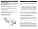
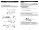
CH. A CH. B
CH. A CH. B
6
UHF-24 RECEIVER
6
CH. A
7
5
9
13
13
1
1
4
4
12
12
15
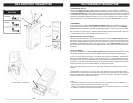
1
1
1
1
2
1
2
4
3
1
4
4
4
8
8
B
8
9
12
12
10
10
10
11
11
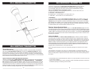
LINK 4™ PLUG-IN TRANSMITTER
Transmitters Set Up
The LINK-4 transmitter requires a single 9V battery to operate. To open the battery compartment,
slide
BATTERY DOOR (31
)
downward to open the cover, exposing the
BATTERY HOLDER (32)
.
Insert a fresh 9V battery according to the correct polarity as indicated on the transmitter body. Slide
back the door onto the original position. Make sure the cover is secured completely. Fresh Alkaline
batteries can last up to 10 hour of operation, but in order to ensure optimum performance, it is
recommended that the batteries should be replaced after 6-8 hours of use.
Handheld Microphone Installation
Step 1 Rotate the transmitter’s threaded
LOCKING RING
(33)
counter-clockwise inward the
transmitter body until it stops.
Step 2 Hold your mic in one hand and the LINK 4 in other.
Step 3 Place your mic into the
XLR CONNECTOR (34)
and push your mic all the way down
untill a click sound.
Step 4 Lock the mic into place with the adjustable threaded
LOCKING RING (33)
by rotating the
ring clockwise, to the top of the transmitter
Step 5 To release the
XLR CONNECTOR (34)
, turn the treaded
LOCKING RING (33)
counter-
clockwise and press the
RELEASE BUTTON (39)
.
Lavalier Microphone Installation
You will need a male XLR to mini male XLR adaptor (Switch-Craft TA-4 or equivalent) to use a
lavalier microphone per the installation instructions. Then plug the lavalier microphone’s mini male
XLR into the adapter. The
PHANTOM POWER SWITCH (35)
should be turned ON for use with a
condenser lavalier mic which requires external phantom powering.
Note: The lavalier microphone you are using must terminate with a mini XLR or full XLR connector
and confi rm to the pin assignments shown below. If they do not, the lavalier mic may not work with
the LINK 4. If you have any questions, please contact your Nady dealer or Nady Systems Service
Department.
The pin assignments on the LINK 4 XLR connector are as shown:
Microphone Operation
To turn it on, slide the
OFF/STANDBY/ON SWITCH (36)
to the STANDBY position fi rst (transmit-
ter on, audio muted) or the ON position (transmitter and audio both on). You could also use your
hardwire microphone audio mute switch afterward. The
BATT LOW INDICATOR LED (37)
will give
a single fl ash in red, indicating usable battery strength. In case of dead or low battery, the LED will
either not go on at all or will stay on continuously, indicating that the battery should be replaced with
a fresh one. To preserve battery life, turn the transmitter off when not in use. To turn off, slide the
OFF/STANDBY/ON SWITCH (36)
to OFF position. No LEDs will light up. The unit is now off.
5
XLR
Connector
Top View
3
1 2
Ground
Phantom Volt. (full 9V battery
voltage) switchable
Mic
Input
680
680
9V
9V
2
3
1