


PRO SM-3
- The Leader in DJ Technology
©1999 Industries - 8 - http://www.numark.com
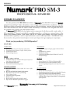
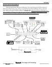
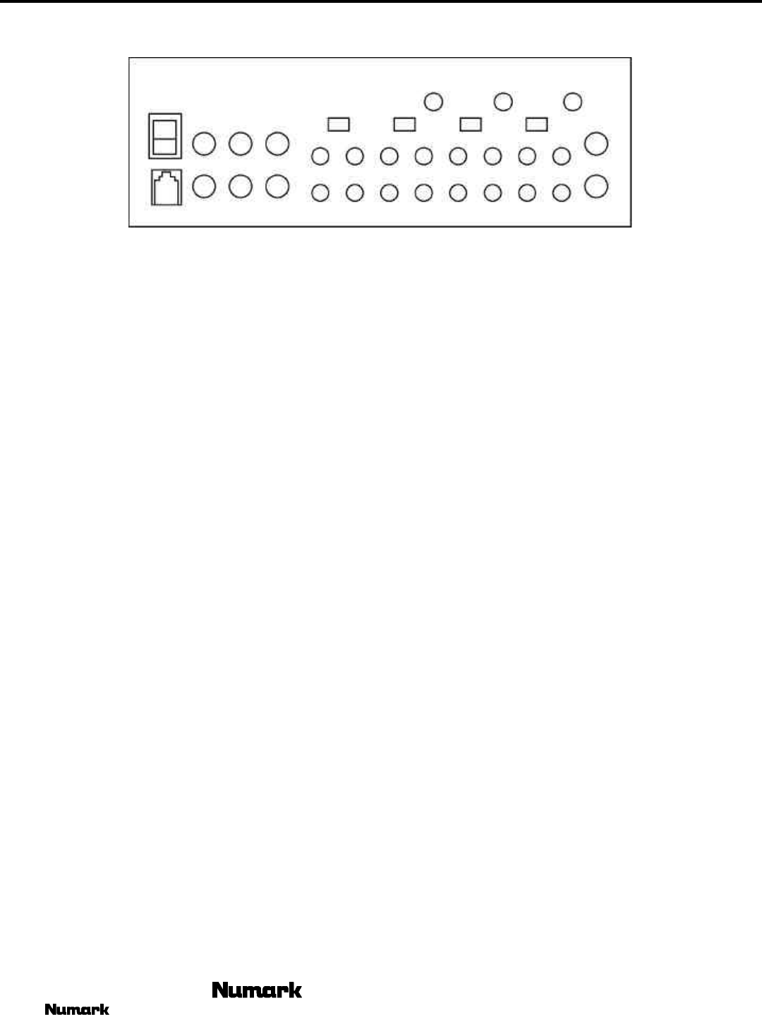
REAR PANEL FEATURES
1
2
3
4
5
6
7
85858
7
7
6610
911
121314
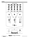
1. Power Switch – to turn unit on after you have turned on
all input devices and before you turn on any devices
attached to the output.
2. Power Supply Input - to plug your power adapter in
before switching on power. See safety precautions on
page 3 for proper treatment of power.
3. Mic Process Send – attach this output to any devices you
would like to process the microphone with. This output is
activated by the front panel mic process button.
4. Mic Process Return – bring your processed mic signal
back in through this input.
5. Phono/Auxiliary Inputs – plug your turntables or line
device in here. Select the AUX/PHONO switch (6) to the
desired input.
6. Phono/Auxiliary switch – select the appropriate position
for your input device. With phono selected the input
signal is fed directly to the PRO SM-1's high-quality
RIAA phono pre-amplifiers so use this input only for
turntables. Line level sources will overload the sensitive
phono pre-amps. Switch this over to the AUX position
for line devices such as CD players and Tape decks.
7. Ground lug - use these connections with your turntables’
grounding cable to avoid signal hum.
8. Line Inputs - to connect stereo audio from HiFi VCRs,
cassette and reel-to-reel tape decks, DAT machines, CD
players, laser discs, tuners, even synthesizers or other
mixing consoles.
NOTE: Plug mono audio sources into both Left and Right
inputs using a “Y" cable connector.
9. Zone Output - an unbalanced output controlled by Zone
Level control on the face panel for extra speakers,
lighting, or recording your mix..
10. Zone Stereo/Mono Switch - allows the user to adjust the
signal accordingly.
11. Unbalanced Main Outputs – program output controlled
by the Master fader knob.
12. Channel Send – The output is determined by pushing the
front panel process selectors next to each channel.
Note: this mixer was design to use one processor for
many channels, If more than one channel is selected than
the signal will bleed across the channels. This can be a
desired effect if you wish to blend wet a dry signal. Sent
signal is captured after the PFL gain and prior to EQ and
Pan adjustments allowing the user total control of the
processed signal.
This output has been designed to work for a variety of
send options.
a. Sampling - the send should be plugged into your
sampler and the signal returned through one of your
inputs.
b. Processing – the send should be plugged into your
external processor. Plug you processor return into
the Channel Return (13).
13. Channel Return – Plug the outputs of your processor to
this input. Set the output level of you processor to match
the signal it receives from the send to ensure smooth
activation. With proper level adjustment you can create
smooth transitions between processed and unprocessed
signal.
Note: If no device is plugged into the return and a signal is
sent to the Channel Send then that signal will not be
interrupted. By plugging into the return jack, the mixer will
route returned signal to replace the sent signal. In this way a
sampler can be used without interrupting live signal. You
also could use this return as a ¼” line input that can be
selected to any channel when the process button is activated.
14. Balanced Outputs - These 1/4" Stereo Main Outputs are
reliable Balanced TRS 1/4" connectors controlled by the
Master fader knob. Power transformers and other devices
which cause magnetic fields can induce hum in audio
cables. This can be best resolved by using balanced lines
where inputs and outputs permit. Balanced lines are also
the most effective means of reducing or eliminating RF or
radio frequency" interference.