7
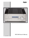
INT-150 Owners Manual
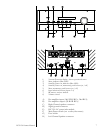
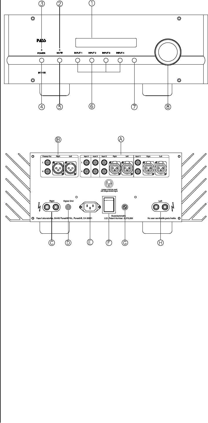
1) Vacuum Florescent display ; shows operational status.
2) Mute, indicator (Blue LED)
3) Stand-by Power on, indicator (Blue LED)
4) Stand-by Power on, momentary push button (on / off)
5) Mute, momentary push-button (on / off)
6) Input selection buttons (inputs 1-4)
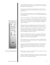
7) IR remote, receiver window
8) Volume control
A) Pre-amplifier inputs (1&2 XLR/RCA , 3&4 RCA)
B) Pre-amplifier outputs (XLR OR RCA)
C) Right Channel speaker connector
D) Signal ground connector
E) IEC 520 AC power inlet module
F) Main Power switch (not a safety disconnect)
G) Fuse holder
H) Left Channel Speaker connector


