


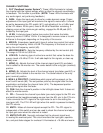
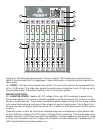
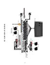
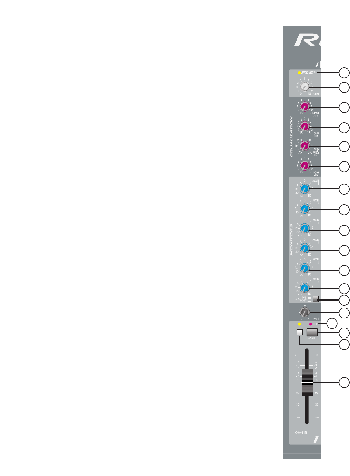
CHANNEL FUNCTIONS:
1. FLS
®
(Feedback Locator System
®
) These LEDs illuminate to indicate
the channel with the highest energy which is often the channel countributing
to feedback. This function is pre-fader. (NOTE: These LEDs illuminate with
any audio signal, not just during feedback.)
2. GAIN: Varies the input gain to allow for a wide dynamic range. Proper
adjustment of the input gain will maximize the signal-to-noise ratio. It should
be set by depressing the PFL switch (#11) and adjusting it for a 0 dBu level
at the L-R meters. At this point, there is 22 dB of headroom remaining. If
clipping occurs at the minimum gain setting, engage the 20 dB pad (#31)
located by the input jack.
3. HI EQ: A shelving type of active tone control that varies the treble
frequency levels ±15 dB at 10 kHz. It is designed to remove noise or to add
brilliance to the signal, depending on the quality of the source.
4. MID EQ: A bandpass (peak/notch) type of active tone control that varies
the midrange frequency levels ±15 dB. The frequency of the boost or cut is
set by the mid frequency control (#5).
5. MID FREQUENCY: Sets the frequency affected by the mid control (#4).
The range is 100 Hz to 3,000 Hz.
6. LOW EQ: A shelving type of active tone control that varies the bass fre-
quency levels ±15 dB at 70 Hz. It will add depth to thin signals, or clean up
muddy ones.
7. MON(1-4): Adjusts the level of the channel signal (post-EQ, pre-fader)
that is added to the monitor mix. The center detent is the unity gain (nominal)
position.
8. MON(5, 6): Adjusts the level of the channel signal (pre-fader, post-EQ, or
post-fader) that is added to the monitor mix. The center detent is the unity
gain (nominal) position.
9. MON 5, 6 PRE/POST: Establishes which signal will be present on the
mon 5 and 6 sends (#8). The out position picks up the signal after the tone
equalization and before the channel fader (#14). The depressed position
picks up the signal after the fader.
10. PAN: Sets the channel’s position in the left/right stereo field. It does not
affect the monitor sends.
11. PFL: Connects the channel’s pre-fader (pre-mute) signal to the PFL mix
and switches the headphone/wedge source from the AFL mix to the PFL mix.
It also connects the PFL signal to the right meter to aid in the setting the
input gain (#2). The PFL LED will light when this switch is pressed to identify
the PFL source.
12. MUTE: Mutes all channel signals except the PFL. The PFL signal is
independent of this switch and can be used to check the channel and adjust
its input gain even when the channel is muted.
13. MUTE/CLIP LED: Normally indicates that the channel signal level
is nearing the overload point. This circuit monitors the input gain, equaliza-
tion, and post-fader stages for overload. It illuminates at +19 dBu and warns
9
13
2
1
3
4
5
6
7
7
7
7
8
8
10
12
14
11
4