


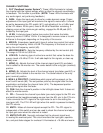
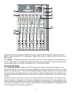
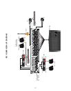

39. PFL LINK: This is a port that makes it possible to parallel two RQ 1606M mixers, increasing
the number of inputs. A shielded stereo (TRS) cord connected between them will cause the two
mixer’s PFL circuits to merge. Then any PFL switch pressed will take over the right meter of the unit
supplying the signal and change the headphone/wedge source on both units.
40. MAIN OUTPUTS: 1/4" unbalanced and XLR balanced outputs of the left and right mixes. The
output level is set by the master left and right faders. The XLR outputs are 4 dB higher in level than
the 1/4" outputs.
41. MAIN MONO OUTPUT: 1/4" balanced (TRS) mono output representing a combination of the
left and right signals.
42. AC MAINS INPUT: Connect the line cord to this connector to provide power to the unit.
Damage to the equipment may result if improper line voltage is used. Operate only with the
specified AC input voltage applied. (See line voltage marking on unit.)
43. POWER: The mixer’s main power switch.
TYPICAL RQ
™
1606M HOOK-UPS:
MONITOR MIXER:
1. Connect the low-impedance microphones (or the mic connectors from the snake cable) to the
XLR inputs. Connect the thru outputs to the house console’s mic inputs. If phantom power is
required, use the power provided by the house console unless it is not available. This will
provide the best performance and cause the fewest problems. If the RQ 1606M provides the
phantom power, it will apply 48 V to all the XLR inputs which may not be desired at the other
console.
2. High-impedance inputs (synth, CD, tape, etc.) should be connected to the 1/4" Hi-Z inputs on
channels 9-16. These are balanced (TRS) and have the same gain as the XLR inputs. High
level signals will require activation of the 20 dB pad switch located by the jack to avoid
clipping.
3. Processors (EQ, delay, or compression) can be connected into the channel 1-8 inserts or to
the monitor 1-6 inserts.
4. Connect the monitor power amp inputs to the monitor outputs. Both balanced and unbalanced
outputs are provided and can be used simultaneously.
5. Connect the engineer’s mix (wedge) power amps to the wedge outputs. This is the same
signal that is at the headphones (AFL or PFL, depending on the switch settings).
6. Recording equipment or other feeds can be connected to the left/right outputs. Monitors 5
and 6 can be set post fader and can also be used for specialized outputs where fader control
is desired.
7. To slave additional monitor mixers, connect the PFL links together (parallel wired) and patch
the slave’s monitor outputs to the master monitor’s line inputs and set the output levels on
the slave to match those on the master. Either console’s PFL signal will take over the wedge
and headphone outputs of both mixers.
8