


11
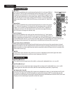
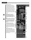
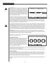
Phantom Power Switch
This switch applies +48 VDC voltage
to the input XLR connectors to power
condenser microphones requiring phan-
tom power. This switch is recessed into
the console and requires a small “tool”
such as a pencil or pen tip to activate. A
regular low impedance dynamic mic such
as the PVM™ 22 will not be harmed. The
Line inputs (49&50) are not connected
to the +48 V supply and are safe for bal-
anced or unbalanced inputs. An adjacent
LED illuminates when Phantom Power is
activated.
Caution:
If phantom power is used, do not
connect unbalanced dynamic micro-
phones or other devices to the XLR
inputs. (Some wireless receivers may be
damaged. Consult their manuals.)
Note:
Make sure the Master Level Faders (40)
are completely down when switching on
the phantom power and when connect-
ing microphones to the Mic inputs to
prevent pops from affecting the loud-
speakers.
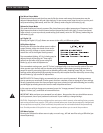
Left, Right, Bus Assign Switches
These post-fader switches determine
where the Group mix signal is being sent.
For example, if each individual drum mic
is assigned to Group 1, depressing the
Left button will send the drum mix to the
Left bus and to the Left Out (54) on the
rear panel.
Mute Switch/Mute-Clip LED
This switch mutes its respective Group
send from the Group channel. This switch
is equipped with a red LED that will il-
luminate when the Group is muted. When
the Mute button is out, the LED functions
as a Clip indicator that will illuminate at 2
dB below clipping.
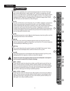
44
19
30
20
21
22
23
24
25
26
47
45
46
38
39
29
41
40
32
31
42
36
35
34
27
37
33
28
43
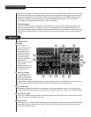
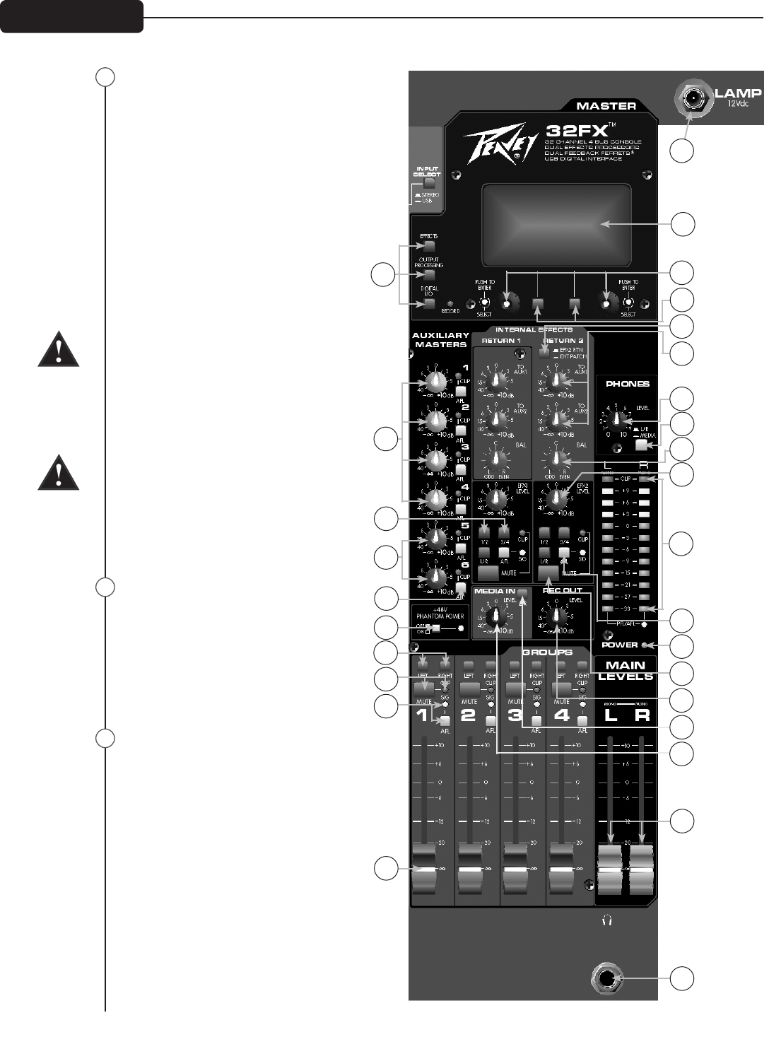
Front Panel
22
24
23