


8
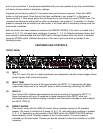
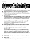
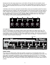
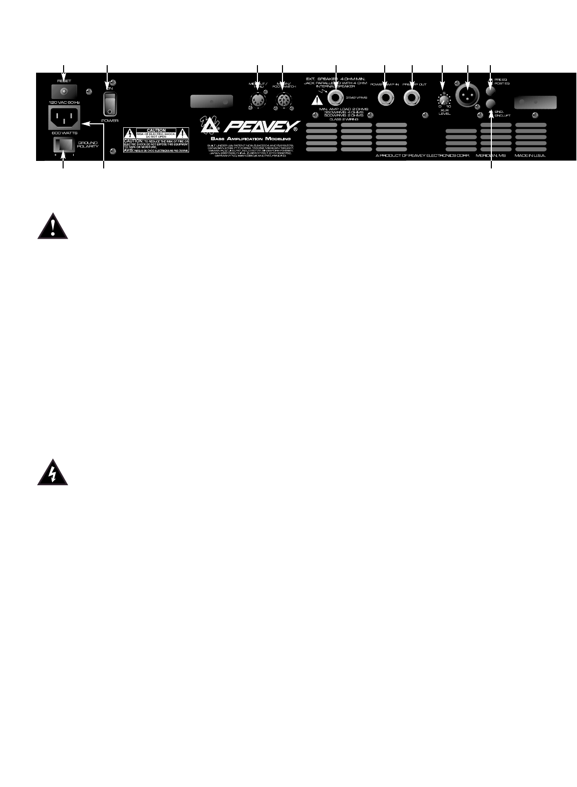
BACK PANEL
(23) CIRCUIT BREAKER RESET
This button resets the internal circuit breaker. Under normal operating conditions, the breaker
should not trip. Conditions such as a short circuit or continuous operation at overload or
clipping may cause this breaker to trip. In the event this occurs, turn off power to the unit and
wait 60 seconds before pressing this button to reset the breaker. Efforts should be made to
determine the cause of the overload. If the breaker continues to trip, the unit should be taken
to a qualified Peavey Service Center for repair.
(24) GROUND POLARITY
This 3-position, rocker-type switch should normally be placed in the center (0) position. If hum
or noise is noticed coming from the speaker enclosure(s), the switch may be placed in the (+)
or (-) position to minimize hum/noise. If changing the polarity does not alleviate the problem,
consult your authorized Peavey dealer, the Peavey factory, or a qualified service technician.
(25) IEC MAINS CONNECTOR
This is a standard IEC power connector. An AC mains cord having the appropriate AC plug
and ratings for the intended operating voltage is included in the carton. The mains cord
should be connected to the amplifier before connecting to a suitable AC outlet.
U.S DOMESTIC AC MAINS CORD
The mains cord supplied with the unit is a heavy-duty, 3-conductor type with a conventional
120 VAC plug with ground pin. If the outlet used does not have a ground pin, a suitable
grounding adapter should be used and the third wire should be grounded properly.
Never break off the ground pin on any equipment. It is provided for your safety.
NOTE: FOR UK ONLY
If the colors of the wires in the mains lead of this unit do not correspond with the colored
markings identifying the terminals in your plug, proceed as follows: (1) The wire that is
colored green and yellow must be connected to the terminal that is marked by the letter E,
the earth symbol, colored green, or colored green and yellow. (2) The wire that is colored
blue must be connected to the terminal that is marked with the letter N or the color black. (3)
The wire that is colored brown must be connected to the terminal that is marked with the
letter L or the color red.
(26) POWER SWITCH
This two-way toggle switch applies mains power to the unit when placed in the ON position.
(27) MIDI OUT / THRU
This standard 5-pin DIN sends MIDI program changes out and/or thru the BAM
™
210. Refer to
the FOOTSWITCH / MIDI section of this manual for more information.
24 25 35
23 26 27 28 29 30 31 32 33 34